
User manual

Code Mercenaries
2
JJ
JJ
WW
WW
22
22
44
44
AA
AA
88
88
LL
LL
--
--
MM
MM
OO
OO
DD
DD
,,
,,
JJ
JJ
WW
WW
22
22
44
44
AA
AA
11
11
00
00
LL
LL
--
--
MM
MM
OO
OO
DD
DD
,,
,,
MM
MM
WW
WW
22
22
44
44
HH
HH
88
88
--
--
MM
MM
OO
OO
DD
DD
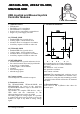
3. Connections
D+, D-, +5V, GND
Connect to USB cable
B0/X0..B7/Y3
Buttons for JW24A8L and JW24A10L. Depending
on the status of J1 connect either up to 8 switches
closing to Gnd, or connect up to 16 switches
between X and Y lines to form a matrix.
To avoid phantom buttons in matrix mode add
diodes in series with the switches. The cathodes of
the diodes have to connect to the Y lines.
B0..B5
Buttons for MW24H8. Connect switches closing to
Gnd.
/Joy
Switch between mouse and joystick mode for
MW24H8. Pull to Gnd to switch to joystick mode.
CH0..CH3
Analog voltage inputs. CH3 is used only on
JW24A8L. Voltage on the CHx inputs must be
between Gnd and Ref.
CH0 = X
CH1 = Y
CH2 = Z or scroll
CH3 = Xr (JW24A8L only)
Ref
Filtered +5V supply for the axes sensors.
Aux0..Aux3
Auxiliary outputs on JW24A8L and JW24A10L.
Can be set under software control, support blink
modes for use with LEDs. See JoyWarrior data
sheet for details.
4. Jumpers
Three solder jumpers are located on the component
side of the modules. JW24A8L-MOD and
JW24A10L-MOD use only jumper 1. All three
jumpers are used by MW24H8-MOD.
4.1 JW24A8L-MOD Jumpers
J1 - Direct
Closing this jumper enables direct mode for the
buttons. By default buttons are run in matrix mode.
J2 - not used
leave open
J3 - not used
leave open
4.2 JW24A10L-MOD Jumpers
J1 - Direct
Closing this jumper enables direct mode for the
buttons. By default buttons are run in matrix mode.
J2 - not used
leave open
J3 - not used
leave open
V1.0.0 August 2nd 2013