
Datasheet


Code Mercenaries
2
LL
LL
EE
EE
DD
DD
--
--
WW
WW
aa
aa
rr
rr
rr
rr
ii
ii
oo
oo
rr
rr
11
11
00
00
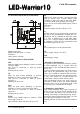
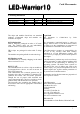
3.1 Mechanical dimensions (LW10-01MOD)
Dimensions in mm
Height at thickest point: < 6.5 mm
Tolerances:
Outer contour: ±0.2mm
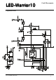
3.2 Pin Descriptions (LW10-01MOD)
Dim
Input for single button dimming. Connect a switch
closing to GND.
(Pot must be connected to Gnd for button
operation.)
Internal pull up resistor.
Up
Input for dual button dimming to increase
brightness. Connect a switch closing to GND.
(Pot must be connected to Gnd for button
operation.)
Internal pull up resistor.
Dwn
Input for dual button dimming to decrease
brightness. Connect a switch closing to GND.
(Pot must be connected to Gnd for button
operation.)
Internal pull up resistor.
PWM
Positive logic PWM output to control a LED
driver, high = lamp on
Open collector output with 4k7 pull up to +5V.
Out
PWM power output. Provides a chopped low side
signal to directly drive constant voltage LED
assemblies. Connect the kathode end of the LEDs
here and the anode to the positive power supply.
May be used as an inverted PWM output to control
a LED driver.
Up to 4 A
Open drain output with 4k7 pull up to +5V.
Pot
Input for center tap of a potentiometer. Connect the
two ends of the potentiometer to GND and Vcc.
LED-Power will be switched off when the center
tap is close to GND and go to full 100% when
close to Vcc. Tying the input to GND will disable
the brightness control via the potentiometer and
allow button inputs to take over.
Vcc
+5V regulated power for the potentiometer.
Vin
Positive supply voltage 5.5 to 40 V.
GND
Ground supply voltage.
4. Dimming by Potentiometer
The position of the potentiometer directly controls
the LED brightness. 0% is selected when the
potentiometer is close to GND and 100% when it is
close to Vcc.
To ensure reliable operation there are dead zones at
either end of the potentiometer range. Any value
within ~10% of GND is considered full off. Values
closer to Vcc than about 90% are considered 100%
on. Any value within 5% of GND disables the
potentiometer control to enable button control.
If the potentiometer input is not used it must be
connected to GND to allow the button dimming
function to take over. A potentiometer with 5 mm
pin spacing can be soldered into the module.
4.1 Dimming by single button
Single button dimming does toggle between off
and last on level if pressed briefly. Holding down
the switch when the lamp is off will result in up
dimming, if the lamp is on dimming will go down.
Pressing the button again when the lamp is on will
dim in the opposite direction as last time.
Dimming will stop at either maximum or minimum
level.
V1.0.1 January 4th 2016