
Datasheet


Code Mercenaries
1
LL
LL
EE
EE
DD
DD
--
--
WW
WW
aa
aa
rr
rr
rr
rr
ii
ii
oo
oo
rr
rr
11
11
00
00
1. Features
• PWM Dimmer Controller
• 730 Hz for flicker free operation
• Potentiometer input
• Dual button and single button dimming
• Programmable power-on value
• Programmable minimum value
• Logarithmic dimming
• Minimal external circuitry
• 5 V supply (chip)
• 5.5 V to 40 V supply (module)
• Max. 4 A PWM output (module)
1.1 Variants
LED-Warrior10 is available in DIL8, SOIC8
packages, and as a module.
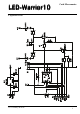
1.2 LW10-01MOD
The LW10-01MOD is a ready to use module that
provides a PWM signal to control a LED driver
and a power output to directly supply constant
voltage LEDs.
1.3 Custom variants
Custom variants are possible for the chips as well
as for the modules.
2. Functional overview
LED-Warrior10 is a dimmer controller for LED
applications. It generates a PWM signal to either
control a LED driver or to directly supply constant
voltage LED modules.
The LED brightness can be controlled either by a
potentiometer, two buttons, or a single button. A
power-on value may be set if the LED should
always switch on to a certain brightness level when
power is applied.
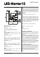
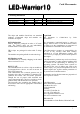
3. Pin Descriptions (Chip SOIC-8 or DIL-8)
Vcc
5 V supply voltage positive input.
GND
Supply voltage negative input.
PWM
730 Hz PWM signal output, positive logic,
high = LED power on.
Duty cycle 0.1% to 100%, constant low for off,
constant high for maximum.
CMOS level output.
/PWM
Inverted PWM signal, negative logic,
high = LED power off.
Duty cycle 0.1% to 100%, constant high for off,
constant low for maximum.
CMOS level output.
Dim
Input for single button dimming. Connect a switch
closing to GND.
Internal pull up resistor.
Up
Input for dual button dimming to increase
brightness. Connect a switch closing to GND.
Internal pull up resistor.
Down
Input for dual button dimming to decrease
brightness. Connect a switch closing to GND.
Internal pull up resistor.
Pot_In
Input for center tap of a potentiometer. Connect the
two ends of the potentiometer to GND and Vcc.
LED-Power will be switched off when the center
tap is close to GND and go to full 100% when
close to Vcc. Tying the input to GND will disable
the brightness control via the potentiometer and
allow button inputs to take over.
Potentiometers should be linear and in the range of
1 kΩ to 200 kΩ . Small potentiometer values ge-
nerate higher standby current.
1
2
3
45
6
7
8
//
//
PP
PP
WW
WW
MM
MM
PP
PP
oo
oo
tt
tt
__
__
II
II
nn
nn
DD
DD
oo
oo
ww
ww
nn
nn
PP
PP
WW
WW
MM
MM
UU
UU
pp
pp
GG
GG
NN
NN
DD
DD
DD
DD
ii
ii
mm
mm
VV
VV
cc
cc
cc
cc
V1.0.1 January 4th 2016
PWM Dimmer Controller