
User manual
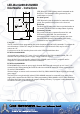

LED-Warrior09-01/02MOD
DALI Master - Instructions
LED-Warrior09 sends lighting control commands on the
DALI bus. The commands can be generated by two
switch inputs or via I2C.
No mains power!
LED-Warrior09 is not designed to be connected to mains
power. The specified voltages have to be observed.
DALI Bus
The DALI bus is connected to the two position header on
the module. The DALI lines are independent of polarity.
Connecting switches
One switch each can be connected between Sw1 and
GND and Sw2 and GND. For most functions a
momentary switch is required, the switches must close
the circuit when operated. The switches must not be
connected to any other current source.
Using I2C
The I2C interface allows programming the switch functions and send DALI commands. To program the
switch functions a USB to I2C dongle (IO-Warrior24-DG or IO-Warrior56-DG) may be used to
connect to a PC.
For direct use of the I2C interface please refer to the LED-Warrior09 data sheet.
LED-Warrior09-01MOD
An external power supply of 5 V (max. 25 mA) is required for the LW09-01MOD variant. The +5V
terminal is the input for the positive supply voltage, GND for negative.
Since the DALI bus is galvanically isolated, LW09-01MOD can be used as a peripheral unit for
computers or controller boards to send DALI commands.
LED-Warrior09-02MOD
LW09-02MOD does extract its power supply from the DALI bus and can supply up to 15 mA 5 V to
external circuits. When planning the DALI bus take into account the maximum current requirement of
25 mA for LW09-02MOD.
Wireless bridges or sensors can be connected to DALI by LW09-02MOD without requiring an external
power supply.
The DALI bus is not galvanically isolated. LW09-02MOD must not be connected to any other power
supply while connected to the DALI bus. When programming LW09-02MOD via I2C either disconnect
it from the DALI bus or use a notebook computer running on battery. To program it while disconnected
from DALI external 5 V must be supplied.
DALI is a registered trademark of ZVEI