
User manual

Code Mercenaries
2
LL
LL
EE
EE
DD
DD
--
--
WW
WW
aa
aa
rr
rr
rr
rr
ii
ii
oo
oo
rr
rr
00
00
55
55
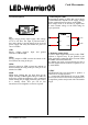
3.3 Pin Descriptions
Vin
Supply voltage positive input. Apply a DC voltage
of 7V to 30V here. The input is protected with a
fuse and a diode to prevent damage from reversed
power supply and safely disconnect the power in
case of a failure.
GND
Supply voltage negative input and ground
reference for MOD input.
LEDa
Positive output for LED, connect the anode of the
first LED of the string to this pin.
LEDk
Negative output for LED, connect the cathode of
the last LED of the string to this pin. This pin is not
identical to GND!
MOD
PWM input. Pulling this pin high shuts off the
output. Feeding a PWM signal with up to 1kHz can
be used to control the brightness of the connected
LEDs. Pulling the pin high permanetly puts LW05
in a standby mode. This pin can be left
unconnected if no brightness control is required.
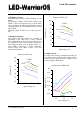
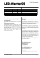
4. Connecting the LEDs
The maximum number of LEDs that can be driven
by LED-Warrior05 depends on the supply voltage
and the combined forward voltage of the LEDs.
Input voltage needs to be about 2.5V higher than
the total forward voltage of the LED string for
proper operation.
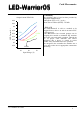
4.1 Reducing output ripple
To reduce output ripple and possibly reduce EMC
problems a capacitor may be put parallel to the
LEDs, preferably connected direct between LEDa
and LEDk of the LED-Warrior05.
The 200mA low ripple version already has such a
capacitor installed on the module to optimise it for
use with OLED.
4.2 EMC
LED-Warrior05 has been designed to produce a
minimal level of EM emissions.
As a component LED-Warrior05 can not be EMC
approved. It has been tested in the configuration of
our AgniLine product and passed with comfortable
margin.
LED1
LEDn
GND
Vin
LEDk
MOD
LEDa
LL
LL
WW
WW
00
00
55
55
V1.0.0 March 21st 2012