
User manual

Code Mercenaries
2
LL
LL
EE
EE
DD
DD
--
--
WW
WW
aa
aa
rr
rr
rr
rr
ii
ii
oo
oo
rr
rr
00
00
44
44
4. Connecting the LEDs
The maximum number of LEDs that can be driven
by LED-Warrior04 depends on the supply voltage
and the combined forward voltage of the LEDs.
Input voltage needs to be about 2.5V higher than
the total forward voltage of the LED string for
proper operation.
Connect the LED strings between the + and -
outputs for each channel.
4.1 EMC
LED-Warrior04 has been designed to produce a
minimal level of RF emissions.
As a component LED-Warrior04 can not be EMC
approved but the EMC tests in a typical
configuration were completely unproblematic. Test
results are available on request.
5. Controlling the LW04
LED-Warrior04 is designed to be controlled via
I2C, DMX-512, or DALI. It can also be
programmed for autonomous sequence operation.
5.1 I2C control
The primary configuration and control interface for
the LED-Warrior04 is the I2C interface. It allows
to set all parameters of the LW04, change the
DMX address, set channel currents for DALI
mode, and to program it for autonomous operation.
5.1.1 I2C addressing
The factory defaul I2C address is xx
The LW04 I2C address can be programmed to any
valid I2C address by sending a broadcast command
(address 0) followed by the register number $04
and the new I2C address.
To change the address LW04 has to be the only
device connected to the I2C.
5.1.2 I2C Registers
I2C communication with the LW04 is done via
registers. The first byte of a write transaction
contains the register number.
A read transaction always reads from the last
accessed register. Reading multiple registers in a
single transaction is possible by reading the
appropriate number of bytes (i.e. reading 4 bytes
from register 2 returns the current settings for all
four channels).
The register address is not changed by a read
command, i.e. if the last register accessed was
register 6 any subsequent read access will go to
that register until the register number is changed by
a write transaction.
All multi byte values are in little endian format
(first byte contains least significant bits).
5.1.3 Register 1: Device Descriptor (read only)
Byte 1: Length Byte
Length of register 1 including the length byte
itself. (Future versions may append additional
data)
Byte 2-5: Serial Number
A unique 32-bit serial number, factory
programmed, LSB first
Byte 6-7: Version
The 16-bit value is composed of the following
halfbytes (LSB first):
<Major-Version>.<Minor-Version>.<Major-
Release>.<Minor-Release>
Byte 8-9: Model
$0004 for standard LED-Warrior04, LSB first.
5.1.4 Register 2 - 5: Channel X Current
The average output current for channel 1/2/3/4 in
milliampere divided by five (i.e. decimal 100
equals 500 mA drive current). Values from 16 to
200 are valid, out of range values will be clipped.
Writing to the channel current registers must be
enabled by setting the enable bit in register 11. Any
write to registers 2-5 are ignored unless bit 7 in
register 11 has been set.
5.1.5 Register 6 - 9: Channel X PWM
A 12-bit little endian value to fade channel 1/2/3/4.
Changes to these registers will only take effect if
I2C is set as dimming input in controller mode 0
register (register 11). LSB first
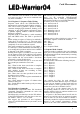
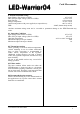
Reg# Bytes R/W Description
1
2
9
1
R
R/W
Device Descriptor
Current Channel 1
3
4
5
6
1
1
R/W
R/W
1
2
R/W
R/W
Current Channel 2
Current Channel 3
Current Channel 4
PWM Channel 0 (12 bit)
7
8
9
10
2
2
R/W
R/W
2
1
R/W
R
11
12
13
14
1
1
R/W
R/W
2
1
R/W
W
PWM Channel 1 (12 bit)
PWM Channel 2 (12 bit)
PWM Channel 3 (12 bit)
LED Status
Controller Mode 1
Controller Mode 2
DMX512 Start Slot
Flash Write / Reset
15 2 / 9 R/W Sequence Mode Table
V0.8.0 June 15th 2015 Draft