
Data Sheet


Code Mercenaries
6
LL
LL
EE
EE
DD
DD
--
--
WW
WW
aa
aa
rr
rr
rr
rr
ii
ii
oo
oo
rr
rr
00
00
44
44
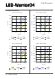
If a sync bit is set the channel waits for the
corresponding channel to come to the end of its
sequence instance before it continues with the next
iteration of its own sequence.
I.e. if Sync1/2 is $04 then channel 1 will wait for
channel 3 to reach the end of its sequence iteration
before it starts its own next iteration. If channel 3
had already reached its sequence iteration end then
channel 1 will continue immediately. Setting
Sync1/2 to $12 will cause channels 1 and 2 to wait
for each other at the end of their sequence iteration
to continue together.
Repeat contains the number of iterations for the
sequence for the corresponding channel. $00
means the sequence will repeat infinitely.
Length sets the number of data sets for each
channel. Data sets are stored consecutively in the
table, starting with those for channel 1. If there are
0 data sets for a channel it takes up no space in the
table.
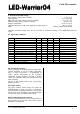
Data sets contain three bytes each:
Byte 0 - PWM LSB
Byte 1 - Time LSB
Byte 2 - PWM/Time MSB
Byte 2 contains a half byte MSB for Time in its
lower half byte and a half byte MSB for PWM in
its upper half byte to get a total 12 bit value for
each PWM and Time.
PWM is the brightness value that should be
reached and Time the time to transition from the
currently active value to that target value in 10 ms
steps. The maximum transition time in one data set
is 40.95 sec. A time value of 0 is invalid and
automatically corrected to 1. Transition between
the values is linear.
For longer transition times or non linear behaviour
multiple data sets may be used.
5.3 DMX512 control
Since DMX512 is a simple lighting protocol it
allows only to set the brightness (PWM) values of
the output channels.
The starting slot number for DMX512 can be set
via I2C. Four consecutive slots are used to control
the brightness of the four channels, unless the
number of channels is reduced via register 17. In
this case only the number of active channels will
use the data slots.
To use DMX512 it must be set as the dimming
source in I2C register 11.
5.4 IEC62386 control
LED-Warrior04 implements the IEC62386 proto-
col according to DIN EN62386-102 and DIN EN
62386-207, as required for control gear for LED.
LED-Warrior04 shows up on the IEC62386 bus as
four separate devices.
To use IEC62386 it must be set as the dimming
source in I2C register 11.
5.5 Tunable White mode
Starting with V1.1.0.0 LED-Warrior04 supports a
tunable white mode when controlled via
IEC62386. The tunable white function is enabled
via Register 17 (chapter 5.1.12).
The tunable white mode is intended to offer a
simpler method than IEC62386 DeviceType 8.
In tunable white mode channels 1 & 2 and 3 & 4
are run as pairs. The cold white LEDs should be
connected to the channels 1 and 3, the warm white
to channels 2 and 4.
The IEC62386 addresses normally used by
channels 1 and 3 will now control the brightness of
the respective channel pair while the addresses
used by channels 2 and 4 will control the color
mix.
This allows to control tunable white luminaires
with simple dimmers.
To run both channel pairs with the same values the
Twin mode can be used. This reduces the required
IEC62386 addresses to two.
6. Regulator efficiency
The regulator efficiency depends on a number of
parameters. Since there are a couple constant
losses independent of the total power delivered by
the regulator the basic rule is that the regulator is
more efficient when used at higher power (i.e.
more LEDs connected). A lower difference
between input and output voltage does also
increase the efficiency.
6.1 Output current
Maximum output current per channel is 1 A.
The actual output current deviates a bit from the
programmed value. The amount of current error
depends on the ration of input to output voltage
and the current setting.
6.2 Reliability
LED-Warrior04 contains no aging components
except the Flash memory. Life expectancy is well
above 100000 hours.
V1.1.3 January 24th 2020