
Data Sheet


Code Mercenaries
5
LL
LL
EE
EE
DD
DD
--
--
WW
WW
aa
aa
rr
rr
rr
rr
ii
ii
oo
oo
rr
rr
00
00
44
44
the second byte contains the error code:
$01 - Write bit has been reset before a complete
table header was transmitted
$02 - Write bit has been reset before a complete
table (number of data sets according to table
header) was transmitted
$04 - More data sets than specified in the table
header have been written
$08 - Write access to other registers terminated the
table writing
$10 - Write attempt to register 15 without write
enable bit being set.
$20 - Length data in table header specify too many
data sets (>81).
5.1.12 Register 17: Extended mode
This register and the associated modes have been
introduced with LED-Warriro04 V1.1.0.0
The added capabilites allow a Tunable White mode
for IEC62386 and can restrict the number of
channels used for IEC62386 and DMX to reduce
address space usage if fewer than all four channels
are required.
This is the format of the one byte register:
Bit 0 - channels LSB
Bit 1 - channels
Bit 2 - channels MSB
Bit 3 - unused, write 0
Bit 4 - unused, write 0
Bit 5 - unused, write 0
Bit 6 - Twin mode
Bit 7 - Tunable White mode
channels is a three bit value setting the number of
active channels to be used for IEC62386 and
DMX. Valid values are 1, 2, 3, 4. Factory default
setting is 4 to use all channels. By reducing the
number of active channels the addresses required
by one LW04 are reduced. If short addresses are
assigned to IEC62386 channels and the number of
channels is reduced then the short address for the
then unused channels will be cleared.
Twin mode is applicable for IEC62386 only and
may be set only when Tunable White mode is
selected and channels is set to 2. If Twin mode is
selected LW04 will drive the channel pairs 1 & 2
and 3 & 4 with identical values.
Tunable White mode is applicable for IEC62386
only. If selected it will run the channels 1 & 2 and
3 & 4 as paires to drive tunable white LED setups.
See chapter 5.5 for details.
Tunable White can only be selected if 4 channels
are active or in combination with Twin mode if 2
channels are selected.
5.1.13 Broadcast commands
LED-Warrior04 implements three I2C broadcast
commands. Broadcast commands are write only
and are send to address 0.
$04 followed by one data byte sets the I2C address
of the LED-Wariror04 to the data byte as the new
I2C address, values 1…127 are valid.
$0A triggers the activation of new brightness
values for all LED-Warrior04 in sync mode (set in
register 11).
$0B followed by one data byte sets the dimming
source on all connected LED-Warrior04
simultaneously. This is useful to synchronously
start sequence mode on several LED-Warrior04.
The data byte has only two active bits:
Bit 0 - unused, write 0
Bit 1 - unused, write 0
Bit 2 - unused, write 0
Bit 3 - unused, write 0
Bit 4 - Dimming source 0
Bit 5 - Dimming source 1
Bit 6 - unused, write 0
Bit 7 - unused, write 0
Dimming source selects which bus is active or if an
autonomous sequence controls the channels:
0b00 - I2C
0b01 - DMX512
0b10 - IEC62386
0b11 - Sequence Mode
5.2 Sequence mode control
If sequence mode is enabled as the active dimming
source and a valid sequence table has been loaded
LED-Warrior04 will work autonomously executing
the sequence table.
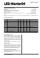
The sequence table is made up of the table header
and up to 81 data sets.
The table header contains the following 10 bytes:
Byte 0 - Sync 1/2
Byte 1 - Sync 3/4
Byte 2 - Repeat 1
Byte 3 - Repeat 2
Byte 4 - Repeat 3
Byte 5 - Repeat 4
Byte 6 - Length 1
Byte 7 - Length 2
Byte 8 - Length 3
Byte 9 - Length 4
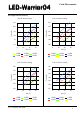
Sync contains the flags for each channel to
synchronize with other channels. Sync 1/2 contains
the sync bits for channel 1 in the lower half byte
and for channel 2 in the upper half byte. Sync 2/3
contains the sync bits for channels 3 and 4.
V1.1.3 January 24th 2020