
Data Sheet


Code Mercenaries
4
LL
LL
EE
EE
DD
DD
--
--
WW
WW
aa
aa
rr
rr
rr
rr
ii
ii
oo
oo
rr
rr
00
00
44
44
5.1.7 Register 11: Controller Mode 1
Bit 0 - Activate channel 1 driver (1 = active)
Bit 1 - Activate channel 2 driver (1 = active)
Bit 2 - Activate channel 3 driver (1 = active)
Bit 3 - Activate channel 4 driver (1 = active)
Bit 4 - Dimming source 0
Bit 5 - Dimming source 1
Bit 6 - Activate sync mode
Bit 7 - Enable current setting
Dimming source selects which bus is active or if an
autonomous sequence controls the channels:
0b00 - I2C
0b01 - DMX512
0b10 - IEC62386
0b11 - Sequence Mode
Activate sync mode selects synchronized dimming
mode when set to 1. If sync mode is enabled any
values written to registers 6…9 are not used until
receiving a broadcast $0A I2C command. This
allows to switch multiple LED-Warrior04 to new
brightness values simultaneously to avoid a wave
effect that would occur with sequential writing.
Enable current setting has to be set to "1" prior to
any writes to registers 2-5. This is intended to
prevent accidentally setting current values that may
damage the connected LEDs. Writing to any other
register than a channel current register does reset
this bit.
5.1.8 Register 12: Controller Mode 2
Bit 0 - unused, always write as 0
Bit 1 - unused, always write as 0
Bit 2 - unused, always write as 0
Bit 3 - unused, always write as 0
Bit 4 - unused, always write as 0
Bit 5 - Sequence write, enables writing register 15
Bit 6 - DMX linear (1 = disable logarithmic curve)
Bit 7 - unused, always write as 0
Sequence write has to be set to enable writing a
new sequence table via register 15. Writing to any
other register than 12 or 15 resets this bit.
Completing the write of a sequence table also
resets this bit.
DMX linear allows to disable the default
logarithmic mapping of DMX 8 bit dimming value
to 12 bit PWM values. If this bit is set the DMX
values will be multiplied by 16 to generate the
PWM values. Default is that the DMX values are
mapped via a logarithmic table to get a human
perception optimized dimming curve.
Bit 7 was removed in V1.1.0.0.
5.1.9 Register 13: DMX512 Start Slot
This 9-bit little endian value is used as the first slot
number of four consecutive DMX slots which set
the PWM channels if DMX512 is set as dimming
input in register 11 (Controller Mode 0)
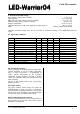
5.1.10 Register 14: Flash Write (write only)
Register 14 allows to write the current settings to
the flash memory. On the next power up reset the
settings will be retrieved from flash memory and
used as default.
Bit 0 - unused, always write as 0
Bit 1 - Store IEC62386 modes in flash
Bit 2 - Store sequence table in flash
Bit 3 - Store DMX start slot number in flash
Bit 4 - Store controller mode in flash
Bit 5 - Store PWM values in flash
Bit 6 - Store current values in flash
Bit 7 - Restore values from flash
Writing any of the bits as "1" does cause the
corresponding currently active parameters to be
written to flash memory.
Writing $80 to this register performs a soft reset.
All controller variables are set to the values stored
in flash memory.
This command resets the LED-Warrior04 to the
same status as a power up does, it can not be
combined with any write commands.
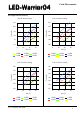
5.1.11 Register 15: Sequence table writing
Sequence mode allows the LED-Warrior04 to
autonomously perform dynamic lighting scenarios.
This can be used to generate a power on fading,
continous changing light situations, flashing, color
changing, or any other lighting applications where
a dynamic lighting without a external controller is
required.
Sequence mode is controlled by a table containing
time and PWM values. The table is specified in
5.2.
Before writing to register 15 it has to be enabled by
setting bit 5 of register 12 to "1". The write bit is
automatically reset when the table has been written
completely or an error condition occured.
Each write transaction to register 15 can contain 1
to 9 data bytes. Write transactions automatically go
to ascending table positions until an error condition
is detected, or the table is complete.
Reading from register 15 returns a two byte status
for the sequence table. If the table has been written
successfully the first byte contains the number of
bytes written and the second holds a checksum
generated by xoring all table bytes.
In case of an error the first byte is set to zero and
V1.1.3 January 24th 2020