
Data Sheet


Code Mercenaries
3
LL
LL
EE
EE
DD
DD
--
--
WW
WW
aa
aa
rr
rr
rr
rr
ii
ii
oo
oo
rr
rr
00
00
44
44
5. Controlling the LW04
LED-Warrior04 is designed to be controlled via
I2C, DMX-512, or IEC62386. It can also be
programmed for autonomous sequence operation.
5.1 I2C control
The primary configuration and control interface for
the LED-Warrior04 is the I2C interface. It allows
to set all parameters of the LW04, change the
DMX address, set channel currents for IEC62386
mode, and to program it for autonomous operation.
5.1.1 I2C addressing
The factory default I2C address is $07 (7 bit
format, to be shifted up one bit to add R/W bit)
The LED-Warrior04 I2C address can be
programmed to any valid I2C address by sending a
broadcast command (address 0) followed by the
register number $04 and the new I2C address.
To change the address LED-Warrior04 has to be
the only device connected to the I2C.
5.1.2 I2C registers
I2C communication with the LED-Warrior04 is
done via registers. The first byte of a write
transaction contains the register number.
A read transaction always reads from the last
accessed register. Reading multiple registers in a
single transaction is possible by reading the
appropriate number of bytes (i.e. reading 4 bytes
starting with register 2 returns the currents for all
four channels).
The register address is not changed by a read
command, i.e. if the last register accessed was
number 6 any subsequent read access will start at
register 6 until the register number is changed by a
write transaction.
All multi byte registers are in little endian format
(first byte contains least significant bits).
5.1.3 Register 1: Device Descriptor (read only)
Byte 1: Length Byte
Length of register 1 including the length byte
itself. (Future versions may append additional
data)
Byte 2-5: Serial Number
A unique 32-bit serial number, factory
programmed, LSB first
Byte 6-7: Version
The 16-bit value is composed of the following
halfbytes (LSB first):
<Major-Version>.<Minor-Version>.<Major-
Release>.<Minor-Release>
Byte 8-9: Model
$0004 for standard LED-Warrior04, LSB first.
5.1.4 Register 2 - 5: Channel X Current
The average output current for channel 1/2/3/4 in
milliampere divided by five (i.e. decimal 100
equals 500 mA drive current). Values from 16 to
200 are valid. Out of range values will be clipped.
Writing to the channel current registers must be
enabled by setting the enable bit in register 11. Any
write to registers 2-5 are ignored unless bit 7 in
register 11 has been set.
5.1.5 Register 6 - 9: Channel X PWM
A 12-bit little endian value to fade channel 1/2/3/4.
Changes to these registers will only take effect if
I2C is set as dimming input in controller mode 0
register (register 11). LSB first
5.1.6 Register 10: LED Status (removed)
Register function has been removed with chip
revision V1.1 since it did not provide consistent
results.
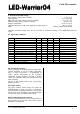
Reg# Bytes R/W Description
1
2
9
1
R
R/W
Device Descriptor
Current Channel 1
3
4
5
6
1
1
R/W
R/W
1
2
R/W
R/W
Current Channel 2
Current Channel 3
Current Channel 4
PWM Channel 1 (12 bit)
7
8
9
10
2
2
R/W
R/W
2
1
R/W
R
11
12
13
14
1
1
R/W
R/W
2
1
R/W
W
PWM Channel 2 (12 bit)
PWM Channel 3 (12 bit)
PWM Channel 4 (12 bit)
not used (removed in V1.1)
Controller Mode 1
Controller Mode 2
DMX512 Start Slot
Flash Write / Reset
15
17
2 / 9
1
R/W
R/W
Sequence Mode Table
Extended mode
V1.1.3 January 24th 2020