
User manual

Code Mercenaries
2
LL
LL
EE
EE
DD
DD
--
--
WW
WW
aa
aa
rr
rr
rr
rr
ii
ii
oo
oo
rr
rr
00
00
11
11
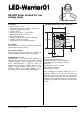
3.1 Pin Descriptions
Vin
Supply voltage positive input. Apply a DC voltage
of 7V to 30V here.
GND
Supply voltage negative input and ground
reference for MOD input.
LEDa
Positive output for LED, connect the anode of the
first LED of the string to this pin.
LEDk
Negative output for LED, connect the cathode of
the last LED of the string to this pin. This pin is not
identical to GND!
MOD
Modulation and dimming input. Can be used for
analog or PWM dimming (see section 5 for
detailed description). Pulling this pin low disables
the LED output and puts the LED-Warrior01 into a
standby mode. This pin can be left unconnected if
no brightness control is required.
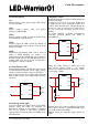
4. Connecting the LEDs
The maximum number of LEDs that can be driven
by LED-Warrior01 depends on the supply voltage
and the combined forward voltage of the LEDs.
Input voltage needs to be about 2V higher than the
total forward voltage of the LED string for proper
operation.
4.1 Reducing output ripple
To reduce output ripple and possibly prevent EMC
problem when the LEDs are mounted not
immediately adjacent to the regulator a capacitor
may be put parallel to the LEDs, preferable
connected direct between LEDa and LEDk of the
LED-Warrior01.
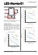
5. Brightness control
The MOD input allows analog or PWM brightness
control of the LEDs.
By applying a 0.3V-2.5V level to the MOD input
the output current can be controlled between 25%
to 200% of the nominal value. Though driving the
current over 100% is to be used very cautiously as
this can exceed the maximum current for the
regulator.
For simple dimming a 100kΩ potentiometer
connecting between MOD and GND is
recommended:
Setting the output current to values above the
100% setting requires either a 2.5V voltage
reference or a voltage divider in the correct relation
to your supply voltage:
Rx = (Vin/2.5) * 100,000
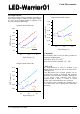
Dimming from 1% to 100% brightness is possible
with an open collector or open drain PWM signal
up to 1kHz connected to MOD.
Example circuit for reducing output current by
PWM:
GND
Vin
LEDk
MOD
LEDa
LL
LL
WW
WW
00
00
11
11
LED1
LEDn
GND
Vin
LEDk
MOD
LEDa
LL
LL
WW
WW
00
00
11
11
LED1
LEDn
100kΩ
GND
Vin
LEDk
MOD
LEDa
LL
LL
WW
WW
00
00
11
11
LED1
LEDn
100kΩ
Rx
V1.0.1 September 11th 2008