
User manual


Code Mercenaries
3
KK
KK
ee
ee
yy
yy
WW
WW
aa
aa
rr
rr
rr
rr
ii
ii
oo
oo
rr
rr
22
22
44
44
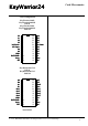
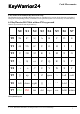
4. Pin Descriptions KeyWarrior24-8/KeyWarrior24-8M
4.1 Pin Functions KeyWarrior24-8/8M
D+, D-
Differential data lines of USB. Connect these
signals direct to the USB cable or type B plug.
Vreg
Regulated 3V output, to be used only for the
purpose of powering the USB D- pull up resistor.
Do not use this pin as a supply for any other circuit
than the pull up resistor.
X0/Scroll, X1/Num, X2/Caps, X[3:7]
Matrix horizontal inputs. These eight lines are read
by KeyWarrior to detect pressed keys.
X0, X1, X2 are also used to drive the Scroll, Num,
and Caps Lock LEDs. An external driver transistor
is required for each LED (see application circuit).
The LEDs will glow faintly when a key on the
same row is pressed.
Internal pull up resistors are activated on device
reset.
Y[0:7]
Vertical matrix outputs. These open drain outputs
are periodically pulled low to detect pressed keys.
No internal or external pull up resistors.
Pull to GND
This pin is used during production of the
KeyWarrior chips, connect to GND.
GND
Power supply ground.
Vcc
Supply voltage.
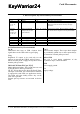
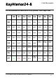
Name
I/O
Type
Pins
Description
D+, D-
Y0, Y1, Y2,
Y3, Y4, Y5,
Y6, Y7
I/O
O
special
open drain outputs
16, 15
1, 2, 3, 4, 24, 23, 22,
21
USB differential data lines
Y lines for key matrix. These lines are periodically
pulled low, between matrix scan they are high
impedance.
X0/Scroll,
X1/Num,
X2/Caps, X3,
X4, X5, X6,
X7
PullToGND
GND
Vcc
I/O
I
inputs with internal
pull ups, X0, X1, X2
open drain I/O
Power supply
Power supply
5, 20, 6, 19, 7, 18, 8,
17
10
X lines for key matrix. Between matrix scan X0,
X1, X2 are used as outputs for the keyboard LEDs
Used during manufacturing, connect to GND
9
14
Ground
Supply voltage
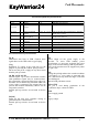
Vreg
NC
O
-
Regulated 3V out
11
12, 13
Power for D- pullup resistor
do not connect
V 1.1.2, December 2nd 2013, for chip revision 1.1.1.4/1.1.1.B and up