
User manual

Code Mercenaries
7
JJ
JJ
WW
WW
22
22
44
44
FF
FF
11
11
44
44
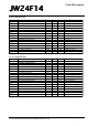
5. DC Characteristics
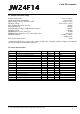
5.1 AC Characteristics
V 1.1.2, November 9th 2015 for Chip Revision V1.0.4.0
Parameter Min Max Units Remarks
V
cc
I
cc
Operating voltage
Operating supply current
4.35 5.25
20
V
mA
I
sb
I
sb
R
up
V
ith
Suspend mode current (chip)
Suspend mode current (module)
Pull-up resistance
Input threshold voltage
8
40%
25
350
μA
μA
24
60%
kΩ
Vcc
Oscillator off
Sensor working
V
oh
V
ol
V
di
USB Interface
Static output high 2.8
Static output low
Differential input sensitivity 0.2
V
cm
V
se
C
in
I
io
Differential input common mode range
Single ended transceiver threshold
0.8
0.8
Transceiver capacitance
Hi-Z State data line leakage -10
3.6 V
0.3 V
V
15kΩ±5% to GND
|(D+)-(D-)|
2.5
2.0
V
V
20
10
pF
μA 0V < Vin < 3.3V, Hi-Z State
R
pu
R
pd
Bus pull-up resistance
Bus pull-down resistance
1.274
14.25
1.326
15.75
kΩ
kΩ
1.3kΩ±2% to Vreg
15kΩ±5%
Parameter Min Max Units Remarks
F
iclk2
Internal clock frequency
USB Driver Characteristics
5.91 6.09 MHz Clock synchronized to USB
t
r
t
r
t
f
t
f
Transition rise time
Transition rise time
75
Transition fall time
Transition fall time
75
300
ns
ns
300
ns
ns
CLoad = 50pF
CLoad = 350pF
CLoad = 50pF
CLoad = 350pF
t
rfm
V
crs
t
drate
Rise/Fall time matching
Output signal crossover voltage
80
1.3
USB Data Timing
Low speed data rate 1.4775
t
djr1
t
djr2
t
deop
t
eopr1
Receiver data jitter tolerance
Receiver data jitter tolerance
-75
-45
Differential to EOP transition skew
EOP width at receiver
-40
165
125
2.0
%
V
1.5225 MBit/s
75
45
ns
ns
100 ns
ns
To next transition
For paired transitions
Rejects as EOP
t
eopr2
t
eopt
t
udj1
t
udj2
EOP width at receiver
Source EOP width
675
1.25
Differential driver jitter
Differential driver jitter
-95
-150
1.50
ns
μs
95
150
ns
ns
Accepts as EOP
To next transition
To paired transition