
User manual

Code Mercenaries
6
JJ
JJ
WW
WW
22
22
44
44
FF
FF
11
11
44
44
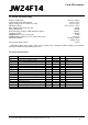
Since the communication with the sensor works via
SPI the same number of bytes as written to the
sensor is read from it at the same time. The data
read from the sensor is returned in a report with the
following format:
Count is the number of bytes read from the sensor,
it may range from 0 to 7. Since the first byte
written to the sensor is always the register address
the first byte read contains random data.
If a pure write transaction to the sensor is done the
read data report is also returned, it will contain
random data but a correct count.
4.5 Calibration
The sensors are factory calibrated for neutral
position and range. Due to mechanical tolerances
during soldering the MEMS sensor element on the
module and mounting the module in the
application a recalibration of the neutral position
may be necessary.
A calibration tool is provided that allows to
calibrate the neutral position. To do the calibration
the sensor needs to be in a stable horizontal
position, with the components facing upwards.
Start the calibration tool and click on "calibrate",
don't move the sensor while the calibration
proceeds.
JoyWarrior24F14 allows calibration to within ±
5mg of zero.
In addition to the neutral position calibration the
gain can also be calibrated, though the calibration
tool does not support setting the gain values. It is
not recommended to change the gain values unless
the process for this type of calibration is properly
understood. Once overwritten there is no way to
retrieve the original gain settings from the sensor.
Writing the gain values can permanently
decalibrate your sensor.
4.6 Sensor parameters
The sensor programming tool allows to set the
relevant sensor parameters which can be used with
the JoyWarrior24F14.
Primary parameters are the measurement range and
the filter setting.
When using the sensor programming tool you have
the option to write to the working registers or the
EEPROM of the sensor. Settings written to the
EEPROM will be stored permanently and will be
used by the sensor after a power down or reset.
Writing to the working registers should be used to
test settings prior to overwriting the factory
settings in the EEPROM. Factory settings can not
be restored from within the sensor.
It is also possible to store the settings to a file. The
settings file may then either be used by the
programming tool or by the automated
programming tool, which is intended to set
multiple sensors to identical parameters.
To use the automatic programming tool you first
have to create a settings file with the programming
tool. Then start the automatic programming tool
and load the settings file. Any JoyWarrior24F14
that gets connected now will automatically get the
settings written to its sensor EEPROM.
4.7 Measurement range
On JoyWarrior24F14 the resolution is always
14bits and the measurement rage can be ±1g, ±
1.5g, ±2g, ±3g, ±4g, ±8g, or ±16g.
When written to the sensor EEPROM the selected
range will automatically be used every time the
sensor is powered up.
4.8 Bandwidth
The sensor element of JoyWarrior24F14 has an
internal filter to reduce the signal bandwidth. The
filter can be set to work as a low pass with cut off
at 10, 20, 40, 75, 150, 300, 600, or 1200Hz.
Additionally a high pass filter with 1Hz cut off and
a band pass for 0.2Hz to 300Hz are available.
Since the data rate is limited to 125 reports per
second it does not make sense to use low pass filter
settings above 75Hz.
Use of the lowest possible bandwidth for the
chosen application is recommended to reduce the
noise level.
0
Count
12
Dat0 Dat1
34
Dat2 Dat3
56
Dat4 Dat5
7
Dat6
V 1.1.2, November 9th 2015 for Chip Revision V1.0.4.0