
User manual

Code Mercenaries
5
JJ
JJ
WW
WW
22
22
44
44
FF
FF
11
11
44
44
4. Device operation
By following the USB HID specifications
JoyWarrior chips are able to work with most
operating systems without the need to supply
special drivers. Any operating system with support
for USB HID devices and game controllers will
have the necessary drivers already in place.
The three axes of the sensor are reported as
joystick axes X, Y, Z with 14 bit resolution.
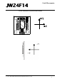
4.1 Axis orientation
In standard operation the sensor data is mapped to
match the standard behaviour of joystick axes. The
signed 14 bit data from the sensor is changed to
unsigned format with 8191 being the neutral
position (i.e. 0g). The orientation of the sensor Y
axis is inverted. This results in a typical axis
orientation for joysticks when the module is in a
position with the components on top and the sensor
facing away from the user.
By pulling the RAW input high the mapping is
switched off so the sensor data is reported
unprocessed. While this is less useful for joystick
operation it may simplify using the data for
measurement applications.
4.1.1 Data filtering
JoyWarrior24F14 uses an internal median filter to
decimate the raw data stream of the sensor (about
2000 values/s) to the USB report rate (125 reports/
s). This also reduces the noise content of the signal.
4.2 Operation with Windows
Any Windows versions 98 and newer and 2000
and newer will work with JoyWarrior. Older
versions of Windows do not support USB. The
support software is tested with Windows 2000 and
newer.
Upon connecting a JoyWarrior based device for the
first time you may be asked to perform the
standard driver install.
After the driver installation has completed you
should be able to see the device in the "Game
Controllers" control panel and be able to access it
via DirectInput. Also a generic HID device should
show up in the device manager.
Do not use the calibration function of Windows, if
the calibration function is used the data reported by
JoyWarrior24F14 gets modified by Windows. To
get rid of a calibration you have to remove the
JoyWarrior24F14 in the device manager, then
unplug, replug, and reinstall it.
Preferably you should read data in the uncalibrated
format. See the programming examples for details.
4.3 Operation with MacOS
On MacOS X access is available via the
HIDManager. Older MacOS versions are not
tested.
There will be no warnings or dialogs when a
properly functioning JoyWarrior based device is
connected under MacOS X, it will simply start to
work.
4.4 Low level sensor access
Reading the sensor data via the joystick interface is
convenient for most applications. However in some
situations a more detailed control over the sensor
may be required, setting the parameters of the
sensor is also not possible via the joystick
interface.
To directly access all registers of the MEMS
sensor JoyWarrior24F14 does have a second
interface (an interface is a logical device in a USB
device) that identifies as a generic HID class
device. Interface 0 is the joystick function that will
be controlled by a system driver. Interface 1
identifies as a generic HID function and can be
controlled from application level on most operating
systems.
For details of the sensor data please refer to the
Bosch BMA180 data sheet.
When accessing the sensor directly make sure you
have understood the working details of the sensor.
There are a couple registers which must not be
overwritten, otherwise the calibration of the sensor
may be lost permanently.
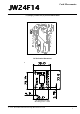
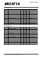
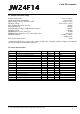
Data is send to the sensor in a report with the
following format:
Flag/Cnt - Contains a flag to disable the joystick
data polling and a data count:
7 - Disable flag, 1 = disable
6 - unused, zero
5 - unused, zero
4 - unused, zero
3 - unused, zero
2 - data count MSB
1 - data count
0 - data count LSB
Data count may be 0 to 7, denoting the number of
bytes to write to the sensor or read from it.
It is recommended to disable the joystick data
polling while communicating with the sensor. So
the first report before actually starting
communication with the sensor should have a $80
in the first byte and no data.
0
Flag/Cnt
12
Dat0 Dat1
34
Dat2 Dat3
56
Dat4 Dat5
7
Dat6
V 1.1.2, November 9th 2015 for Chip Revision V1.0.4.0