
User manual

Code Mercenaries
6
JJ
JJ
oo
oo
yy
yy
WW
WW
aa
aa
rr
rr
rr
rr
ii
ii
oo
oo
rr
rr
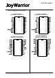
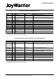
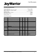
4.4 Pin descriptions
D+, D-
Differential data lines of USB. Connect these
signals direct to a USB cable. D- requires a pull up
resistor connecting to VREG, see application
circuits for details.
VREG
Supplies 3.3V for the USB D- pull up resistor.
Don't use this pin to supply power to external
circuitry, it does only supply sufficient current for
the pull up resistor.
B0..B7 (JoyWarrior24A8-8)
Inputs for the buttons. Connect contacts closing to
ground.
Internal pull up resistors.
X0/B0..X3/B3 or X0/B0..X7/B7
Matrix row inputs for the buttons. In direct mode
these pins work as direct button inputs, active low,
use contacts closing to ground.
Internal pull up resistors.
Y0/B4..Y3/B7 or Y0/B8..Y3/B11
Matrix column outputs or button inputs for direct
mode. In matrix mode these pins are periodically
pulled low to determine the status of the buttons.
In matrix mode all buttons must be decoupled with
diodes, see application circuit for details.
In direct mode these pins act as active low inputs,
connect contacts closing to ground.
Open drain outputs or inputs with internal pull up
resistor.
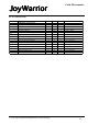
Left, Right, Up, Down (JoyWarrior24GP32)
Inputs for the direction pad. Connect contacts
closing to ground.
Internal pull up resistors.
/CS, SCLK, Din, Dout (JoyWarrior24A8L/
A10L)
Signals to connect to the external A/D converter.
JoyWarrior 24A10L requires an external Maxim
MAX1249 A/D converter, JoyWarrior24A8L
requires a Maxim MAX1113.
Internal pull up resistors.
/Pull to GND
This pin is used during production of the
JoyWarrior chips, connect to GND.
A0, A1 (JoyWarrior24A8-x)
The center taps of the pots and a capacitor are
connected to these two pins. The pins are used to
charge the capacitor and measure the time it takes
to discharge the capacitor via the pots.
See application circuits for details.
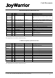
XR1, XR2, YR1, YR2, ZR1, ZR2
(JoyWarrior24A8-x)
These outputs connect to the outer taps of the pots.
One of them is pulled low at a time to measure
how long it takes to discharge the capacitor via the
pot.
Axis values get smaller when the pot center tap
gets closer to the tap connected to the nR1 pin, i.e.
resistance between nR1 and A0, A1 gets smaller.
RAW (JoyWarrior24A8-x)
Pulling this pin to Vcc disables the autocalibration
and autocentering function. The chip will then
report the raw axis data. This can be useful during
design test or for applications that can't accept the
autocalibration or autocentering feature.
Internal weak pull down resistor.
Direct (all except JoyWarrior24A8-x)
Pulling this pin high disables the matrix scanning
for the buttons and instead uses all button pins as
as direct button inputs for up to 8 or 12
(JW24GP32) buttons pulling to GND.
All button input pins have internal pull ups.
Aux0..Aux3 (JoyWarrior24A8L/A10L)
Auxiliary outputs, active low. Each pin is capable
to sink up to 50mA (70mA combined for all pins).
Push-Pull outputs.
GND
Power supply ground.
Vcc
Supply voltage.
V 1.1.0, July 1st 2010 for Chip Revision V1.0.4.0 and up