
User manual


Code Mercenaries
8
JJ
JJ
oo
oo
yy
yy
WW
WW
aa
aa
rr
rr
rr
rr
ii
ii
oo
oo
rr
rr
5.8 Joystick axis orientation
USB specifies the axis orientation as follows:
For the X axis values should increase for left to
right movement, Y axis values increase for far to
near movements (i.e. pulling the stick gets you
larger values), Z axis values should increase for
high to low movement.
5.9 Non Joystick Applications
USB does allow a Human Interface Device
controller to very detailed specify the function of
axes and buttons. This gives a game controller
device the option to specify a certain axis to be a
throttle or break or something else.
The standard JoyWarrior chips are for general use,
so the analog axes variants just specify X, Y, Z and
the switch inputs are defined as being just buttons.
We can modify the controllers to define axes as
other inputs, like gas or rudder pedals or support
hat switches etc.
However not all available usages are supported by
all operating systems and programs. Windows for
instance supports only a small subset of the
simulation controls page.
If you have special requirements, please contact us
about modifications.
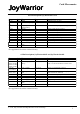
5.10 Auxiliary outputs on JW24A8L/A10L
The JoyWarrior24A8L and JoyWarrior24A10L
chips have four auxiliary outputs that may be used
to drive LED indicators or for other applications.
Due to the significant current sinking cabability of
the outputs they are defined as being active low.
Setting the outputs is done by sending a four byte
Feature report to the joystick device. In most cases
this can be done via standard file I/O functions.
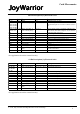
The outputs are set by one byte each, the first byte
sets Aux0, second Aux1 etc.
The bits in the bytes do have the following
meaning:
7 - reserved, write 0
6 - reserved, write 0
5 - reserved, write 0
4 - reserved, write 0
3 - Invert blink mode
2 - reserved, write 0
1 - Mode MSB
0 - Mode LSB
The mode bits determine the behaviour of the
output. Following are the combinations (MSB/
LSB):
00 - Output idle (high)
01 - Output static on (low)
02 - Fast blink mode (1/8th second on/off)
03 - Heart beat blink mode
Heart beat mode switches the output low for 1/16th
second, then high for 1/16th, again low for 1/16th
and then idles high for 13/16th seconds.
The invert bit reverts the ouput status for the blink
modes (no effect on static on/off), this allows to
have two indicators blink in an exactly alternating
pattern.
The output status and blinking is maintained by the
JoyWarrior withoput further host interaction until a
new configuration is send. All outputs go to idle
when the JoyWarrior enters suspend mode.
V 1.1.0, July 1st 2010 for Chip Revision V1.0.4.0 and up