
User manual


Code Mercenaries
2
II
II
OO
OO
--
--
WW
WW
aa
aa
rr
rr
rr
rr
ii
ii
oo
oo
rr
rr
Content
1.0 Features 1
1.1 Variants 1
1.2 Custom variants 1
2.0 Functional overview 1
2.1 Product selection matrix 3
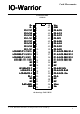
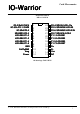
3.0 Pin Configurations 5
4.0 Pin Descriptions IO-Warrior40 8
4.1 Pin Descriptions IO-Warrior24 8
4.2 Pin descriptions 9
4.3 Special mode pin functions 9
4.3.1 IIC Mode pins 10
4.3.2 LCD Mode pins 10
4.3.3 SPI Mode Pins (IOW24 only) 10
4.3.4 RC5 Mode Pins (IOW24 only) 10
4.3.5 LED Matrix Mode Pins 11
4.3.6 Switch Matrix Mode Pins (IOW40 only) 11
4.3.7 Capture Timer Mode Pins (IOW24 only) 11
5.0 Device Operation 12
5.1 Accessing IO-Warrior 12
5.2 IO-Warrior communication 12
5.3 IO-Warrior input behaviour 12
5.5 IO-Warrior output behaviour 12
5.6 Using pins as inputs or outputs 12
5.7 Power supply 13
5.8 Suspend 13
5.9 Remote Wakeup 13
5.10 Special mode I/O 14
5.10.1 IIC Special mode function 14
5.10.2 LCD Special mode function 16
5.10.3 SPI Special mode function (IOW24 only) 17
5.10.4 Getting current pin status 18
5.10.5 Receiving RC5 IR codes (IOW24 only) 18
5.10.6 Driving LED matrix 18
5.10.7 Switch Matrix Mode (IOW40 only) 19
5.10.8 Capture Timers (IOW24 V1.0.3.0 only) 20
7.1 Packaging info 24
7.2 USB VendorID and ProductID 24
7.3 Serial numbers 24
7.4 Currently shipping versions 24
8.2 Warning about USB cables 27
8.3 Jumpers on the IOW40 Starter Kit 27
8.3.1 Jumpers on the IOW24 Starter Kit 27
8.4 Adding custom circuits 27
8.5 Example circuits 27
8.5.1 Drivers 27
8.5.2 Isolating inputs 28
8.5.3 Protecting inputs and outputs 28
8.5.4 Using the LCD function 28
9.0 Package Dimensions 30
10.0 ESD Considerations 32
10.1 EMC Considerations 32
11.0 Revision History 33
12.0 Legal Stuff 34
V 1.1.0, December 2nd 2013, for chip revision V1.0.3.0 and up