
User manual

Code Mercenaries
32
II
II
OO
OO
--
--
WW
WW
aa
aa
rr
rr
rr
rr
ii
ii
oo
oo
rr
rr
10.0 ESD Considerations
IO-Warrior has an internal ESD protection to
withstand discharges of more than 2000V without
permanent damage. However ESD may disrupt
normal operation of the chip and cause it to exhibit
erratic behaviour.
For the typical office environment the 2000V
protection is normally sufficient. Though for
industrial use additional measures may be
necessary.
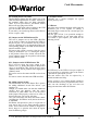
When adding ESD protection to the signals special
care must be taken on the USB signal lines. The
USB has very low tolerance for additional
resistance or capacitance introduced on the USB
differential signals.
Series resistors of 27 may be used alone or in
addition to some kind of suppressor device. In any
case the USB 2.0 specification chapter 6 and 7
should be read for detailed specification of the
electrical properties.
10.1 EMC Considerations
IO-Warrior uses relatively low power levels and so
it causes few EMC problems. The most important
issue is to provide a very clean layout for the
power supply. IO-Warrior runs at 12MHz internal
clock rate, this can cause current spikes if the
supply lines are not carefully layed out.
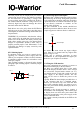
To avoid any EMC problems the following rules
should be followed:
• Keep the PCB traces from the resonator to the
chip pins as short as possible.
• Put the 100nF ceramic capacitor right next to
the power supply pins of the chip and make sure
the PCB traces between the chips power pins
and the capacitor are as short as possible.
• Run the power supply lines first to the capacitor,
then to the chip.
• Connect the second ground pin in the shortest
possible way to the first ground pin. No other
things may have precedence over this.
• Keep the two USB signal lines close to each
other, route no other signal between them. USB
uses differential signalling so the best signal
quality with lowest RF emission is achieved by
putting these lines very close to each other.
V 1.1.0, December 2nd 2013, for chip revision V1.0.3.0 and up