
User manual

Code Mercenaries
29
II
II
OO
OO
--
--
WW
WW
aa
aa
rr
rr
rr
rr
ii
ii
oo
oo
rr
rr
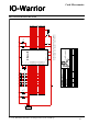
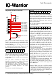
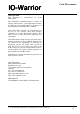
This pinout is for the IO-Warrior40!
Pot1 is used to set the contrast of the LCD. T1 and
R1 drive the power for the backlighting. This
circuit is sufficient for displays which have a LED
type backlighting.
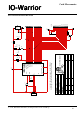
To access the display the first thing you have to do
is enable the LCD special mode function. To do
this you send the following report to interface 1:
This will enable the LCD function and pull the /On
pin low. The backlight of the display should now
be on. A line of dark rectangles should be visible
on the display. If this is not the case you may have
to adjust Pot1.
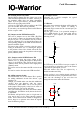
Next you need to initialize the display. This
depends a bit on the type of display you use and
what operating mode you want to put it in.
Lets assume we do have a two line display. We
want the display cleared and the cursor displayed
as well as a flashing character at the cursor
position.
To do this we send the following report:
The $03 in the flags position tells IO-Warrior to
write 3 bytes to the command register of the LCD.
$38 sets the data bus of the LCD to 8 bits and
enables two line mode. $01 is the clear command
which empties the display buffer. $0F enables the
display, enables the underscore cursor and the
flashing cursor position.
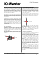
Now we want to display a couple characters. Send
the following report:
$86 in the flags tells IO-Warrior to write 6 bytes to
the data register of the LCD. The next six bytes are
ASCII codes. "ABCDEF" should now appear in
the display. Sending the same report again will
result in another "ABCDEF" being displayed after
the first one.
To access the second line it may be necessary to
set the display RAM address first. HD44780 based
displays do have storage for up to 80 characters.
This storage is divided into two display lines. The
first 40 bytes of RAM are used for the first line,
data for the second line is in the second 40 bytes.
Depending on the actual module characters in the
display RAM can end up at different places in the
display and not necessarily at places that seem to
be logical in the first moment.
For instance a 16x1 display may use display RAM
from the second line for the second half of its
single display line. Such a display will have to be
treated as a two line display even though the user
sees only one line.
Displays with four lines typically drive the first
and third line from the first 40 bytes in display
memory and the second and fourth line from the
second 40 bytes.
We recommend to download the HD44780 data
sheet from the Hitachi website for more details.
Also there are many information resources on the
internet, just use your favorite search engine and
look for HD44780.
Attention: When you have an LCD module
connected to IO-Warrior you should be aware that
the idle status of the IO-Warrior pins may cause
the LCD module to assume a valid read going on.
So the I/O pins connected to the LCDs data lines
may be pulled to a non-zero state.
LCD
1
2
3
4
5
6
7
8
9
10
11
12
13
14
15
16
+5V
10k
POT1
BC307
T1
47
R1
P0.3/LCD-RS
P0.4/LCD-R/W
P0.5/LCD-E
P1.0/LCD-DB0
P1.1/LCD-DB1
P1.2/LCD-DB2
P1.3/LCD-DB3
P1.4/LCD-DB4
P1.5/LCD-DB5
P1.6/LCD-DB6
P1.7/LCD-DB7
P0.2/LCD-/On
ReportID
$04 out
12
$01 $00
34
$00 $00
56
$00 $00
7
$00
ReportID
$05 out
12
$03 $38
34
$01 $0F
56
$00 $00
7
$00
ReportID
$05 out
12
$86 $41
34
$42 $43
56
$44 $45
7
$46
V 1.1.0, December 2nd 2013, for chip revision V1.0.3.0 and up