
User manual

Code Mercenaries
28
II
II
OO
OO
--
--
WW
WW
aa
aa
rr
rr
rr
rr
ii
ii
oo
oo
rr
rr
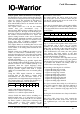
The same circuit may be employed if you want to
control a DC electric motor. Any inductive load has
the bad behaviour of generating a voltage with
reverse polarity upon being switched off. If this is
not shorted with the diode the voltage will rise to
relatively high levels that can damage the driver
transistor and/or the IO-Warrior.
Both drivers are active only when the IO-Warrior
pulls the port pin low. This makes sure that power
consumption is minimized during initialization and
suspend mode.
WAR NI NG ! I f yo u in te nd to sw it ch ma in s v ol tag e
with a relais keep in mind that electric shocks at
mains level can be lethal. Also faulty circuits with
high voltage and/or power are a fire hazard. Such
designs or experiments should be done only by
properly trained people. Code Mercenaries is not
responsible for damage or injury caused by such
experimentation.
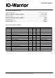
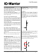
8.5.2 Isolating inputs
In situations where you want to control devices
operating on a different power supply than the
USB of your computer or where electrical isolation
is required for other reasons it is advisable to work
with opto couplers.
Opto isolating outputs is discussed in the former
paragraph. Opto isolating inputs is similarly simple
to achieve:
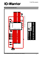
8.5.3 Protecting inputs and outputs
IO-Warrior has a limited protection against electro
static discharge in the chip. Though this protection
is only sufficient in situations where the electronics
is protected inside an enclosure and where the pins
are not directly connected to contacts on the
outside of this enclosure.
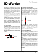
Any pins connected to the outside should have
additional protection added to them. In most cases
a simple suppressor with two diodes is sufficient:
The diodes will short circuit any input voltages
lower than 0V to ground and any higher than
supply voltage to +5V.
Usually this is sufficient protection in most
environments. If your requirements are higher you
should use opto couplers for isolation.
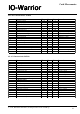
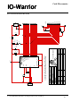
8.5.4 Using the LCD function
Just a few components are necessary to connect a
HD44780 based display to the IO-Warrior.
One thing you should check first is how much
current the display modules draws. If the current
does exceed the suspend mode current (see 5.7)
you should provide a high side switch to cut the
power supply to the display module. The /On
signal can be used to enable the power to the
display.
Typically HD44780 based display modules have a
16 pin connector that has a standard pinout.
However you should in any case check the data
sheet of the particular display you want to use to
make sure you will not destroy the display due to a
different pinout.
Following is the circuit necessary to connect a
LCD module with backlighting. This assumes that
the display does not draw more power than USB
allows for suspend state as the power supply to the
LCD is connected direct.
This circuit is already included on the PCB of the
IOW24KIT.
Your input
Px.x
Px.x ex ter nal pin
+5V
V 1.1.0, December 2nd 2013, for chip revision V1.0.3.0 and up