
User manual

Code Mercenaries
27
II
II
OO
OO
--
--
WW
WW
aa
aa
rr
rr
rr
rr
ii
ii
oo
oo
rr
rr
8.2 Warning about USB cables
The IO-Warrior Starter Kit does ignore one of the
USB standard requirements for cables. Contrary to
the standard which does not allow detachable
cables on low speed devices, IO-Warrior Starter
Kit has a B-type plug on the PCB.
As long as a full speed cable according to the USB
specs is used this will cause no problems.
If you make your own design based on IO-Warrior
do use a captive cable.
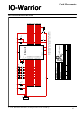
8.3 Jumpers on the IOW40 Starter Kit
The row of jumpers next to the LEDs (JP1-JP8)
can be used to connect or disconnect the LEDs to
the pins of port 3. If you intend to use any of these
pins for something else you should disconnect the
corresponding jumper as the LED would otherwise
interfere with the signal.
JP9 next to the switch is used to select the power
setting of IO-Warrior (see 5.7). Setting the jumper
to the position closer to the switch selects the low
power (100mA) mode, the far position selects high
power (500mA) mode.
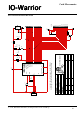
8.3.1 Jumpers on the IOW24 Starter Kit
JP1 is used to select the power setting of IO-
Warrior (see 5.7). Setting the jumper to the position
closer to the IOW24 Chip selects the low power
(100mA) mode, the far position selects high power
(500mA) mode.
JP2 can be used to disconnect the IR receiver from
P0.0.
JP3 can be used to disconnect the LED from P0.3.
8.4 Adding custom circuits
The bread board area on the Starter Kit is perfect
for adding additional circuits like drivers, opto
couplers, etc.
Though you should make sure that this additional
circuitry does not interfere with the power
restrictions of USB. Make sure to set the power
mode jumper JP9 properly so the host is aware of
how much power your circuit will draw.
Also your circuit may not draw more than 100mA
(including the IO-Warrior itself) before the device
is initialized.
IO-Warrior will pull all its pins to a high state on
reset and it does so also when entering suspend
mode. Your external circuit should be designed so
that it drops to a quiscent state when all signals
from IO-Warrior go high.
8.5 Example circuits
Following are a couple examples for typical
circuits you may need.
8.5.1 Drivers
One of the most common situations will be that the
IO-Warrior pin is not capable of sinking a
sufficiently high current for the external part you
want to control.
Only the pins of Port 3 are powerful enough to
drive a LED directly. If you want other pins to
drive LEDs or opto couplers you should use the
following circuit:
The LED may be the LED of an opto coupler. It
may be necessary to adapt the value of the resistor
to the LED or optocoupler you use.
LED and resistor may also be replaced by a
suitable incandescent lamp.
Driving a relais is very similar, though a diode in
reverse direction has to be put parallel to the coil to
make sure the discharge of the coil does not
damage the transistor and/or IO-Warrior:
270
Px.x
+5V
Px.x
+5V
V 1.1.0, December 2nd 2013, for chip revision V1.0.3.0 and up