
User manual

Code Mercenaries
20
II
II
OO
OO
--
--
WW
WW
aa
aa
rr
rr
rr
rr
ii
ii
oo
oo
rr
rr
5.10.8 Capture Timers (IOW24 V1.0.3.0 only)
IO-Warrior24 has two capture timers that allow the
measurement of the time between rising and falling
edges of a signal. The resolution of the timers is
4sec, the accuracy depends on the USB clock
from which IOW24 derives its internal clock with
a tolerance of ±1.5%.
The capture timers use a 24 bit free running
counter that gets incremented every 4
microseconds. When a rising or falling edge occurs
on a timer input (i.e. the logic level on the pin goes
from low to high or from high to low) the value of
the counter is stored and send in a report. The
relative timing between events can be measured.
When reaching maximum count the counter rolls
over and starts again from zero. To measure events
longer apart than 67.108864s additional time
keeping must be done on the host computer.
Two capture timers are available that can be used
individually or at the same time. They use the same
24 bit counter, so no timing offset between the two
timers exists.
Periodic events up to 250Hz on one timer or up to
125Hz on both timers simultaneously can be
tracked with no edges lost, if no other special mode
functions of IOW24 are used at the same time. At
higher frequencies events can be lost due to
overrun (see below).
The maximum frequency for periodic signals that
can be handled without IOW24 locking up due to
internal overload is above 100kHz (lockup is not
permanent when the signal frequency drops
IOW24 will resume to work normally). To reliably
measure periodic signals faster than a couple
100Hz it is recommended to use an external gating
circuit.
Using the LED matrix function or sending/
receiving data via IIC during a capture timer
measurement can cause the timer value to be
corrupted due to too high internal processing load.
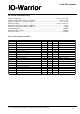
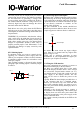
The capture timers are enabled and disabled by a
report with ID $28 that is sent to interface 1:
enable = $00 disables both timers
enable bit 0 = 1 enables capture timer A
enable bit 1 = 1 enables capture timer B
Always disable the timers before switching to a
different enable state, i.e. if only timer A is in use
and you want to activate timer B too, first disable
the timers (enable = $00) before activating both
timers (enable = $03). This applies for all
combinations of switching between enable
combinations of the timers.
The capture timers can not be used at the same
time as the RC5 receiver. Timer B shares the pin
with the IIC function and can not be used at the
same time as the IIC function.
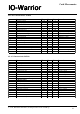
Timer data is returned when a rising and/or falling
edge was detetced on either timer input pin. Timer
A uses report ID $29 to return its data, timer B uses
report ID $2A:
flags is a bitfield that signals which edges have
been detected and if there was an overrun
condition. An overrun occurs if another rising or
falling edge is detected on the same timer before
the data for the last edge data could be send via
USB. IO-Warrior24 can return one data packet
every 8msec, this limit applies to the data
combined from both capture timers and all other
special mode functions of IOW24.
In case of an overrun the first edge that has been
detected is reported, subsequent edges are ignored
until the data has been send off via USB. There is
no guarantee that IOW24 can reliably detect an
overrun if the events happen too fast.
The meaning of the flag bits is as follows:
7 - Capture B rising edge overrun
6 - Capture B falling edge overrun
5 - Capture A rising edge overrun
4 - Capture A falling edge overrun
3 - Capture B rising edge detected
2 - Capture B falling edge detected
1 - Capture A rising edge detected
0 - Capture A falling edge detected
The report contains data fields for a fall and rise
event of the respective timer. The flags indicate if
the data is valid, i.e. if the flag for rising edge
detected is not set then the rising edge data is not
valid.
The flag bits for both timers are always included in
both reports.
fall0, fall1, fall2, rise0, rise1, rise2 contain the
counter status at the time of the event, xx0 is the
least significant byte, xx2 is the most significant
byte.
ReportID
$28 out
12
enable $00
34
$00 $00
56
$00 $00
7
$00
ReportID
$29 in
12
flags fall0
34
fall1 fall2
56
rise0 rise1
7
rise2
ReportID
$2A in
12
flags fall0
34
fall1 fall2
56
rise0 rise1
7
rise2
V 1.1.0, December 2nd 2013, for chip revision V1.0.3.0 and up