
User manual

Code Mercenaries
18
II
II
OO
OO
--
--
WW
WW
aa
aa
rr
rr
rr
rr
ii
ii
oo
oo
rr
rr
5.10.4 Getting current pin status
Due to the way Windows implements HID support
IO-Warrior is unable to continuously send its
status. HID class devices do have a function that
allows the host to set the rate at which reports
should be repeated if there is no change to the data.
Windows does this rate to zero for IO-Warrior,
which means IO-Warrior may send data only if
there are changes.
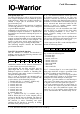
To be able to get the current status from IO-
Warrior it does support a Special Mode Function
that always returns the current status of all pins.
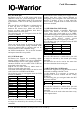
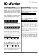
To get the port status just send a report with ID
$FF to interface 1:
This will result in the current pin status to be
returned immediately in an input report with ID
$FF with the following format:
IOW24 will always return $00 for Port2 and Port3.
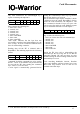
5.10.5 Receiving RC5 IR codes (IOW24 only)
IO-Warrior 24 has the capability to use a simple IR
receiver module to receive IR remote control codes
according to the RC5 format.
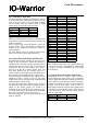
To enable the receiver function a report with ID
$0C is sent to interface 1:
enable = $01 enables the RC5 function, enable =
$00 disables it again.
Any time IO-Warrior receives a valid RC5
command it does return the received data in an
input report with ID = $0C:
data contains the six bits of the command, addr
contains the five address bits as well as the start bit
(always 1), /C6 command bit and toggle bit.
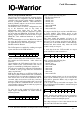
5.10.6 Driving LED matrix
IO-Warrior has the capability to drive a LED
matrix of up to 8x32 with the aid of a few simple
external driver chips.
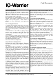
To enable the reciever function a report with ID
$14 is sent to interface 1:
enable = $01 enables the LED function, enable =
$00 disables it again.
Data to be displayed in the matrix is written in 8
rows of 4 bytes each:
row denotes the matrix row number. 0 to 7 are
valid row numbers. Row number 0 is the data that
will be displayed when out1 of the sourcing X
driver is active. Row 0, data0 bit 0 is what the
programming examples assume to be the upper left
corner.
LED Matrix and LCD function can not be used at
the same time since they share pins. If one of the
functions is enabled it will prevent the other
function to get activated.
The LED Matrix function is present in IO-Warrior
since chip revision V1.0.2.0. However the initial
implementation has some problems when being
used with OHCI type USB host controllers. Only
V1.0.2.1 and later is recommended for LED matrix
use with OHCI host controllers (all Macintosh
computers use OHCI, for PCs mainly VIA chipsets
are concerned).
ReportID
$FF out
12
$00 $00
34
$00 $00
56
$00 $00
7
$00
ReportID
$FF in
12
Port0 Port1
34
Port2 Port3
56
$00 $00
7
$00
ReportID
$0C out
12
enable $00
34
$00 $00
56
$00 $00
7
$00
ReportID
$0C in
12
data addr
34
$00 $00
56
$00 $00
7
$00
ReportID
$14 out
12
enable $00
34
$00 $00
56
$00 $00
7
$00
ReportID
$15 out
12
row data0
34
data1 data2
56
data3 $00
7
$00
V 1.1.0, December 2nd 2013, for chip revision V1.0.3.0 and up