
User manual

Code Mercenaries
17
II
II
OO
OO
--
--
WW
WW
aa
aa
rr
rr
rr
rr
ii
ii
oo
oo
rr
rr
5.10.3 SPI Special mode function (IOW24 only)
IO-Warrior24 has a hardware SPI interface
enabling it to talk to many peripheral devices.
IOW24 supports SPI master mode.
To enable the SPI function a report with ID 8 is
sent to interface1:
enable = $00 disables the SPI and $01 enables it.
"mode" contains flags specifying the operating
mode for the SPI:
7 - unused, write zero
6 - unused, write zero
5 - unused, write zero
4 - unused, write zero
3 - CPOL
2 - CPHA
1 - data rate MSB
0 - data rate LSB
The data rate select bits set the clock speed at
which IO-Warrior is driving SCK:
00 - 2MBit/sec
01 - 1MBit/sec
10 - 0.5MBit/sec
11 - 0.0625MBit/sec
CPHA works together with CPOL to specify which
clock edges are used to drive and sample data bits.
CPOL = 0 causes SCK to idle low between data
bytes, CPOL = 1 makes SCK idle high.
CPHA = 0 causes data to be driven on the first
clock edge and sampled on the second edge. CPHA
= 1 causes data to be driven on the second edge
(first bit gets driven before the first edge) and
sampled on the first edge.
Enabling SPI takes P0.3..P0.7 out of the control of
interface zero.
SPI does always shift data in and out
simultaneously. So there is only one command to
send data out of SPI that does also result in the
same number of bytes being read in and returned to
the host. if the intention is to only read data from
an external device it is still necessary to shift out
the same number of dummy bytes to that device.
IOW24 does not allow to use SPI and LCD at the
same time. If LCD is enabled at the time a
command to enable SPI is received the command
is ignored. This means none of the SPI commands
will be executed when received nor will they send
any response. IOW24 will acknowledge that it
received the report with the command but not
execute the corresponding function and not send
any reports in reaction to the command.
Data transfers on the SPI are initiated by a report
with ID 9:
"flags" contains the following bits:
7 - useDRDY, 1 = do handshake
6 - SSactive, 1 = /SS stays active
5 - ignoreDRDY, 1 = first byte ignores /DRDY
4 - unused, zero
3 - unused, zero
2 - data count MSB
1 - data count
0 - data count LSB
"useDRDY" allows to enable a handshaking signal
that allows the slave to signal if and when it is
ready to accept or send data.
If "useDRDY" is = 1 IO-Warrior will check for the
/DRDY signal to be low before it starts shifting a
data byte. If the slave wants to pause the data
transmission it has to pull /DRDY high before the
end of the current byte transfer.
Upon starting a data transfer it may be desired to
send the first byte without the slave signalling /
DRDY low. By setting "ignoreDRDY" to 1 the
first byte of this report is sent to the slave without
checking /DRDY. Prior to shifitng the next byte
IO-Warrior will check the status of /DRDY.
"data count" has the number of bytes to shift, only
values 1-6 are valid, others will be ignored.
IO-Warrior assertes /SS before starting to shift the
first data byte of this report and will deassert it
after completing the last byte, unless bit 6
"SSactive" is = 1. If "SSactive" is set /SS will stay
asserted after the last byte of the report has been
transfered, allowing more than 6 bytes to take part
of a single transfer.
Data shifted in by IO-Warrior during a transaction
is returned in a report with ID 9:
"count" holds the number of valid bytes in the
report.
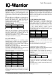
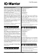
ReportID
$08 out
12
enable mode
34
$00 $00
56
$00 $00
7
$00
ReportID
$09 out
12
flags data
34
data data
56
data data
7
data
ReportID
$09 in
12
count data
34
data data
56
data data
7
data
V 1.1.0, December 2nd 2013, for chip revision V1.0.3.0 and up