
User manual

Code Mercenaries
16
II
II
OO
OO
--
--
WW
WW
aa
aa
rr
rr
rr
rr
ii
ii
oo
oo
rr
rr
5.10.2 LCD Special mode function
The LCD special mode function supports display
modules that are compatible with the HD44780
controller and several graphic display controllers
that use a compatible interface . This controller is
made by Hitachi and has set the de-facto standard
for alphanumeric LCD modules.
The modules come in various configurations with
up to 80 characters total in any kind of
arrangement from single line to four lines.
Displays with more than 80 characters typically
use more than one HD44780. IO-Warrior does not
directly support modules with more than a single
HD44780, some additional hardware is required
for this.
It is recommended to read the HD44780 manual
for using the LCD function. Also have a look at
our application note AN5: Driving Display
Modules with IO-Warrior.
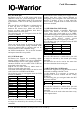
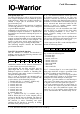
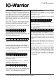
The LCD function is enabled by sending an output
report with ID 4 to the USB interface 1:
enable = $00 disables the LCD function. enable =
$01 enables the LCD function, other values are
reserved.
Upon enabling the LCD function the Pins are put
under control of the LCD function and can no
longer be controlled by SetReport to interface 0.
The /On pin is pulled low when the LCD function
is enabled, it will go high when the IO-Warrior
enters suspend state.
IOW24 does not allow to use SPI and LCD at the
same time. If SPI is enabled at the time a command
to enable LCD is received the command is ignored.
This means none of the LCD commands will be
executed when received nor will they send any
response. IOW24 will acknowledge that it received
the report with the command but not execute the
corresponding function and not send any reports in
reaction to the command.
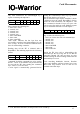
To write data to the connected LCD module an
output report with ReportID 5 is written with the
following format:
"flags" contains the following bits:
7 - RS, Register Select bit
6 - unused, zero
5 - unused, zero
4 - unused, zero
3 - unused, zero
2 - data count MSB
1 - data count
0 - data count LSB
The status of the RS bit is used to set the RS line to
the LCD module. This allows access to the
Instruction register (RS=0) or Data Register (RS=
1) of the LCD module.
With "data count" the number of bytes to be
written is specified. IO-Warrior will write up to six
data bytes to the register specified by the RS bit.
The Busy bit of the LCD module is automatically
checked and data written only when the LCD
module is ready to accept it.
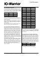
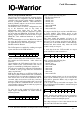
To read data from the LCD module an output
report with ID 6 is sent to interface 1:
"flags" contains the following bits:
7 - RS, Register Select bit
6 - unused, zero
5 - data count MSB
4 - data count
3 - data count
2 - data count
1 - data count
0 - data count LSB
RS specifies which register is to be accessed. Data
count sets the number of bytes to be read off the
LCD (will be ignored if RS=0, only a single read
will be done then).
Up to 63 bytes can be read with one request. The
data read from the LCD module is returned in input
reports with ID 6:
"count" specifies the number of bytes returned in
this report. If more than 6 bytes are requested the
data will be returned in multiple reports.
With chip revision 1.0.3.0 a 16ms timeout for the
Busy bit of the LCD has been added.
ReportID
$04 out
12
enable $00
34
$00 $00
56
$00 $00
7
$00
ReportID
$05 out
12
flags data
34
data data
56
data data
7
data
ReportID
$06 out
12
flags $00
34
$00 $00
56
$00 $00
7
$00
ReportID
$06 in
12
count data
34
data data
56
data data
7
data
V 1.1.0, December 2nd 2013, for chip revision V1.0.3.0 and up