
User manual

Code Mercenaries
11
II
II
OO
OO
--
--
WW
WW
aa
aa
rr
rr
rr
rr
ii
ii
oo
oo
rr
rr
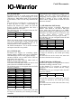
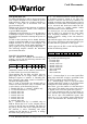
4.3.5 LED Matrix Mode Pins
IO-Warrior supports driving a LED matrix with up
to 8x32 LEDs. The LED matrix mode can not be
used at the same time as the LCD mode. IOW40
can use either 16x8 key matrix mode or LED
matrix mode, never both at the same time.
When the LED Matrix function is enabled these
pins will no longer be affected by the normal port
setting command.
/OE is driven high when IO-Warrior enters the
suspend mode. The external driver should then
disable to stay within the USB power limits for
suspend mode.
For more details on how to control a LED matrix
please refer to the separate application note.
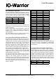
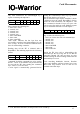
4.3.6 Switch Matrix Mode Pins (IOW40 only)
IO-Warrior40 supports scanning of a 8x8 or 16x8
matrix of keys or switches. When this function is
enabled P3.0..7 will turn off their internal pull up
resistors and will be used as the Y lines that are
periodically driven to Gnd voltage level. P2.0..7
will serve as the X0..7 matrix inputs, they will
keep their internal pull up resistors active so a
closed switch in the matrix will pull down the X
line when the corresponding Y line is driven low.
If the 16x8 mode is enabled P1.0..7 will be used as
additional X lines, serving as X8..15. The 16x8
matrix mode can be used only if the LCD and LED
matrix functions are not in use.
To allow more than two switches to be closed at
the same time and still be able to faultlessly detect
which of the matrix points are closed it is
necessary to insert a diode in series with every key
or switch in the matrix. The kathodes of the diodes
have to be connected to the Y lines (P3.0..7).
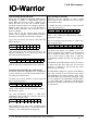
The following pins get reassigned when the key
mode is enabled:
When IO-Warrior40 enters the suspend mode the
X and Y lines will be pulled high by internal pull
up resistors. Closing a switch/key does not wake
the IO-Warrior.
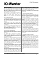
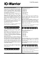
4.3.7 Capture Timer Mode Pins (IOW24 only)
IO-Warrior24 has two capture timers that can
measure falling and rising edges with a resolution
of 4sec. When this function is turned on P0.0 and/
or P0.1 will be used for the timers and be no longer
available for standard I/O. P0.0 is shared between
the RC5 receiver and capture timer A. P0.1 is
shared between the IIC function and capture timer
B. The RC5 receiver and the capture timers can not
be used at the same time since they share internal
resources on the chip.
Function IOW24 IOW40
/OE
Strb
P1.0
P1.1
P1.0
P1.1
Clk
Data
P1.2
P1.3
P1.2
P1.3
Function IOW24 IOW40
X0
X1
-
-
P2.0
P2.1
X2
X3
X4
X5
-
-
P2.2
P2.3
-
-
P2.4
P2.5
X6
X7
X8
X9
-
-
P2.6
P2.7
-
-
P1.0
P1.1
X10
X11
X12
X13
-
-
P1.2
P1.3
-
-
P1.4
P1.5
X14
X15
Y0
Y1
-
-
P1.6
P1.7
-
-
P3.0
P3.1
Y2
Y3
Y4
Y5
-
-
P3.2
P3.3
-
-
P3.4
P3.5
Y6
Y7
-
-
P3.7
P3.7
Function IOW24 IOW40
Capture A
Capture B
P0.0
P0.1
-
-
V 1.1.0, December 2nd 2013, for chip revision V1.0.3.0 and up