
User manual

Code Mercenaries
10
II
II
OO
OO
--
--
WW
WW
aa
aa
rr
rr
rr
rr
ii
ii
oo
oo
rr
rr
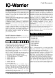
4.3.1 IIC Mode pins
IO-Warrior can act as an IIC master with about
100kbit/sec data rate (actual throughput is about
750bytes/sec). Multi-Master mode is not supported
by IO-Warrior, it has to be the only master on the
IIC.
Since the IIC bus in IO-Warrior is software driven
it does not have as stable a clock timing as
hardware IIC masters have. Make sure that the
devices you drive with IO-Warrior don't have a
problem with some clock jitter.
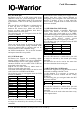
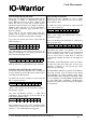
The following pins get reassigned when the IIC
function is enabled:
These pins will no longer be affected by the data
sent via the normal port setting command. Both
pins have internal pull up resistors and can be
connected direct to IIC compatible chips.
On IOW24 simultaneous use of the IIC function
and capture timer B is not possible.
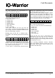
4.3.2 LCD Mode pins
IO-Warrior has support for controlling alpha-
numeric display modules based on or compatible
with HD44780 as well as some graphic displays.
Attention: IOW24 can use either LCD or SPI but
never both at the same time.
IOW40 can use either 16x8 key matrix mode or
LCD, never both at the same time.
LCD mode and LED matrix mode can not be used
at the same time on IOW24 and IOW40.
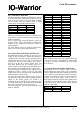
The following pins get reassigned when the LCD
function is enabled:
When the LCD function is enabled these pins will
no longer be affected by the normal port setting
command.
/On should be used to enable power supply to LCD
modules that have high current demand or
backlighting. The /On signal is low when the LCD
function is enabled, it does go high when IO-
Warrior enters suspend mode or when the LCD
function is disabled.
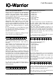
4.3.3 SPI Mode Pins (IOW24 only)
IO-Warrior24 supports a hardware SPI master
interface. This means it can talk to SPI slave
devices with a data clock speed of up to 2MHz.
Actual data throughput is significantly lower since
USB allows only 100 reports per second to be send
to low speed devices (actual system
implementations allow 125 reports per second)
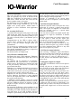
The following pins get reassigned when the SPI
function is enabled:
When the SPI function is enabled these pins will
no longer be affected by the normal port setting
command.
SPI and LCD can not be used at the same time
since these functions share some pins.
4.3.4 RC5 Mode Pins (IOW24 only)
IO-Warrior24 supports receiving IR remote control
commands according to the RC5 code.
For this function it is necessary to connect an
appropriate IR receiver module like the Vishay
TSOP1736.
The following pins get reassigned when the RC5
function is enabled:
When the RC5 function is enabled these pins will
no longer be affected by the normal port setting
command.
RC5 mode can not be used at the same time as any
of the capture timers.
Function IOW24 IOW40
SCL
SDA
P0.1
P0.2
P0.6
P0.7
Function IOW24 IOW40
/On
RS
P0.4
P0.5
P0.2
P0.3
R/W
E
Data0
Data1
P0.6
P0.7
P0.4
P0.5
P1.0
P1.1
P1.0
P1.1
Data2
Data3
Data4
Data5
P1.2
P1.3
P1.2
P1.3
P1.4
P1.5
P1.4
P1.5
Data6
Data7
P1.6
P1.7
P1.6
P1.7
Function IOW24 IOW40
/DRDY
/SS
P0.3
P0.4
-
-
MOSI
MISO
SCK
P0.5
P0.6
-
-
P0.7 -
Function IOW24 IOW40
RxD P0.0 -
V 1.1.0, December 2nd 2013, for chip revision V1.0.3.0 and up