
User manual


Code Mercenaries
8
II
II
OO
OO
--
--
WW
WW
aa
aa
rr
rr
rr
rr
ii
ii
oo
oo
rr
rr
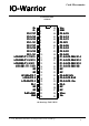
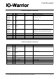
4.0 Pin Descriptions IO-Warrior40
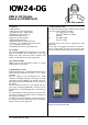
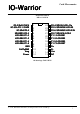
4.1 Pin Descriptions IO-Warrior24
Name
I/O
Type
Pins (DIL40)
Description
D+, D-
P0.0, P0.1,
P0.2, P0.3,
P0.4, P0.5,
P0.6, P0.7
I/O
I/O
special
I/O open drain, internal
pullup
1, 2
23, 18, 24, 17, 25, 16,
26, 15
USB differential data lines
First I/O Port. P0.0 is used at power on to select low
or high power mode
P1.0, P1.1,
P1.2, P1.3,
P1.4, P1.5,
P1.6, P1.7
P2.0, P2.1,
P2.2, P2.3,
P2.4, P2.5,
P2.6, P2.7
P3.0, P3.1,
P3.2, P3.3,
P3.4, P3.5,
P3.6, P3.7
PullToGND
I/O
I/O
I/O open drain, internal
pullup
I/O open drain, internal
pullup
I/O
I
I/O open drain, internal
pullup
27, 14, 28, 13, 29, 12,
30, 11
31, 10, 32, 9, 33, 8,
34, 7
Second I/O Port
Third I/O Port.
35, 6, 36, 5, 37, 4, 38,
3
19
Fourth I/O Port. P3.7 must be pulled high with a
100k resistor for proper operation of the chip.
Strong drive outputs, capable of driving LEDs
direct.
Used during manufacturing, connect to GND
GND
Vcc
XOut
XIn
Power supply
Power supply
O
I
20, 39
40
Ground
Supply voltage
22
21
On chip oscillator output
On chip oscillator input
Name
I/O
Type
Pins
Description
D+, D-
P0.0, P0.1,
P0.2, P0.3,
P0.4, P0.5,
P0.6, P0.7
I/O
I/O
special
I/O open drain, internal
pullup
16, 15
1, 2, 3, 4, 24, 23, 22,
21
USB differential data lines
First I/O Port.
P1.0, P1.1,
P1.2, P1.3,
P1.4, P1.5,
P1.6, P1.7
Power
PullToGND
GND
I/O
I
I/O open drain, internal
pullup
Input internal pull
down
I
Power supply
5, 20, 6, 19, 7, 18, 8,
17
12
Second I/O Port
Used to set high or low power mode
10
9
Used during manufacturing, connect to GND
Ground
Vcc
Vreg
NC
O
Power supply
Regulated 3V out
-
14
11
Supply voltage
Power for D- pullup resistor
13
do not connect
V 1.1.0, December 2nd 2013, for chip revision V1.0.3.0 and up