User Manual Note: Refer to the CR2500/CR3500 User Manual, Appendix C: Programming Code Matrix for all CR3500 configuration option codes.
Statement of Agency Compliance The Code Reader™ 3500 has been tested for compliance with FCC regulations and was found to be compliant with all applicable FCC Rules and Regulations. IMPORTANT NOTE: To comply with FCC RF exposure compliance requirements, this device must not be colocated or operate in conjunction with any other antenna or transmitter. CAUTION: Changes or modifications not expressly approved by the party responsible for compliance could void the user’s authority to operate the equipment.
Code Reader™ 3500 User Manual Copyright © 2012 Code Corporation. All Rights Reserved. The software described in this manual may only be used in accordance with the terms of its license agreement. No part of this publication may be reproduced in any form or by any means without written permission from Code Corporation. This includes electronic or mechanical means such as photocopying or recording in information storage and retrieval systems. NO WARRANTY. This technical documentation is provided AS-IS.
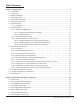
Table of Contents Chapter 1 - Getting Started ........................................................................................................................... 1 1.1 - Introduction............................................................................................................................................. 2 1.2 - Unpacking................................................................................................................................................ 2 1.
2.9 - Continuous Trigger Optimization Matrix...............................................................................................33 2.10 - Continuous Scan..................................................................................................................................33 2.11 - Continuous Scan Settings...................................................................................................................34 2.11.1 - Continuous Scan - Sleep Time Out.........................
4.10 - Lock-out Link Mode.............................................................................................................................47 Chapter 5 - Advanced Decode Performance ................................................................................................ 48 5.1 - Set Targeting Zone Tolerances...............................................................................................................49 5.2 - Windowing.......................................................
Chapter 1 - Getting Started Save Settings C004387_07_CR3500_ User_Manual - 1
1.1 - Introduction With new high-performance bar code reading technology, a graphic display and rugged keyboard, the Code Reader™ 3500 (CR3500) is the most advanced portable data terminal on the market today. The CR3500 decodes bar codes faster and offers features not found in other readers, including new automatic glare reducing illumination technology.
1.3 - Battery Installation Attaching and Detaching the Lithium Ion Battery The CR3500 can be purchased with a 1950 mAH Lithium Ion battery. To install battery, make sure the battery is in the correct position (Figure 1.1). Place the plastic tab of the battery into the reader slot (Figure 1.2). Push the battery in and slide the locking mechanism down (Figure 1.3). Note: Batteries ships with approximately 50% battery life. Fully charge battery before use.
1.6 - Keypad/Icon Overview The chart below shows key/button functions.
The chart below shows all of the icons for CodeViewer™ software and their definitions. Icon Description Power Icons 50% to 100% capacity of battery 20% to 50% capacity of battery 0% to 20% capacity of battery – recharge battery as soon as possible Battery is recharging No icon is displayed when battery blank is used with a cabled reader Connection Icon Reader is connected physically or wirelessly to a receiving device (computer, handheld, etc.
1.7 - Batch Operation 1.7.1 - Introduction The CR3500 features a batch mode for applications requiring a portable reader. Batch mode allows a user to store scanned data to the reader’s non-volatile memory. The user may transfer the data to a host computer when needed. To utilize batch functionality you will need to a battery cartridge or battery handle. The CR3500may be programmed to operate in three different batch modes: 1.
Transferring and Deleting Data There are three different codes to transfer and delete data in memory. 1. Transfer All Data in Memory - This code will send all data in memory everytime the code is scanned. 2. Transfer Only Unsent Data in Memory - This code will send only the data in memory that hasn’t already been sent when the code is scanned (ONLY works in Send & Buffer and Send & Log modes). 3.
1.8 - Cabled Operation 1.8.1- Introduction The CR3500 is a Multi-Interface Unit (MIU) and is available with USB and RS232 cables. All of the cables are connected to the CR3500 with a 8-pin DIN connector (Figure 1.8). Figure 1.8 Hand Held CR3500 - To install a cable directly to the CR3500, correctly line up the 8-pin DIN connector into the back end of the reader. The arrows on the connector should be facing down (Figure 1.9).
1.8.2 - CR3500 as a USB Keyboard To connect the CR3500 to your host computer via USB interface: 1. Attach the USB cable to CR3500 (Figure 1.13). 2. There is no need to power of the computer (Figure 1.14) Connect the USB cable to a USB port on the computer (Figure 1.15). 3. Once properly connected, the CR3500 will power on and beep. 4. Scan the below code (M049_03) for USB Keyboard Mode: USB Keyboard Factory Reset 7. Save Settings Scan the Save Settings Code (M188_02) Figure 1.
1.8.2.1 - Addional USB Communication Settings (continued) Scan the following codes to set the appropriate USB communication setting: USB Keyboard USB Downloader USB Native Two Way Mode USB Virtual COM 1 Way Mode USB HID POS (Terminal ID 131) 1.8.2.
1.8.3 - PS/2 Cable Installation Guide 1. Power off the computer. If you disconnect the computer’s keyboard while it is powered on, your computer will lock up. 2. Attach the the PS/2 cable to the CR3500. 3. If you have a cabled keyboard, detach the keyboard cable from the computer and connect that same connector to the female connection on the CR3500 PS/2 cable (Figure 1.16). 4. Now connect the male CR3500 PS/2 connector into the keyboard port on the computer (Figure 1.17). 5. Power on the computer.
1.8.4 - RS232 (Serial) Cable Installation Guide 1. Attach the RS232 (Serial) Cable to the CR3500. 2. Connect the RS232 (Serial) cable to a serial port on the computer (Figure 1.18). There is no need to power off the computer. 3. The RS232 (Serial) interface has an optional 5V/1.5A power supply (Figure 1.19). If you have a power supply, plug the power supply adapter into the RS232 (Serial) cable and then plug the power adapter into a wall socket (Figure 1.20). Figure 1.18 Figure 1.19 Figure 1.20 4.
1.8.4.1 - Additional RS232 Communication Data Bit Settings Scan the following codes to set the appropriate data bit: 7 Data Bits 8 Data Bits (Default) 1.8.4.2 - Additional RS232 Communication Baud Rate Settings Scan the following codes to set the appropriate baud rate: 1200 2400 4800 9600 19200 38400 57600 (Default) 115200 1.8.4.
1.9 - Bluetooth Radio Operation 1.9.1 - Introduction The CR3500 features a Bluetooth® wireless radio. The radio allows for point-to-point wireless communication with other Bluetooth devices that support serial port protocol (SPP). If keyboard entry is necessary, CodeXML® Router will need to be installed. The following guide will give you general instructions on connecting your CR3500 to a desktop or laptop computer with a Bluetooth radio.
1.9 - Bluetooth Radio Operation (Continued) Radio Range and Transferring Data The CR3500 radio is a Class 1 device. If connected to another Class 1 device the reader has roughly a 100 meter (300 feet) line of sight operating range. If connecting to a Class 2 or Class 3 device, the operating range may drop to match the lower range. Once a reader is connected, a serial application must be opened (HyperTerminal) unless CodeXML® Router is installed.
1.9 - Bluetooth Radio Operation (Continued) Permanently Establishing a Connection Scan the Save Settings Code at the bottom of the page to make the RF settings (including which device to connect to) permanent on the reader: Disconnecting from the Device You may force disconnection by reading the disconnect code below (The CR3500 may not appear disconnected in the slave Bluetooth connection manager for 10 – 15 seconds after the command is issued).
1.9.4 - Bluetooth Radio Time Out Settings Scan the following codes to set the period of time before the Bluetooth Radio will go into sleep mode due to inactivity: Note: Increasing the time before the reader will time out will decrease battery life. 90 Seconds (Default) 5 Minutes 10 Minutes 30 Minutes 1 Hour 2 Hours 15 Minutes 1.9.
1.9.7 - Configuration for Belkin Bluetooth Manager Software (Version 1.4.2.10) In this version of the Belkin Bluetooth Manager software, you must disable the authentication feature to connect a Code Reader 3500. Follow the steps below: 1. Double click on the Bluetooth icon in the system tray. In the My Bluetooth Places Screen, select Advanced Configuration. 2. Select the Local Services tab and double click on the Bluetooth Serial Port. Inder the General tab unselect the Secure Connection box.
1.9.7 - Configuration for Belkin Bluetooth Manager Software (Continued) 3. Your local service Bluetooth Serial Port profile should now read “Not Required” 4. Open the “Accessibility” Tab and verify that “All Devices” are allowed to connect (this is the default setting). You should now be able to connect your Code Reader 3500.
1.9.8 - Configuration for Toshiba Bluetooth Stack Instructions 1. 2. Navigate to the Control Panel and Open the Bluetooth Local COM Port Icon. Identify the Appropriate Com Port owned by the LocalCOM-Server[SerialPort(TOSHIBA LocalCOM)] Owner. 3.
1.9.8 - Configuration for Toshiba Bluetooth Stack Instructions (Continiued) 3a. Go to http://www.codecorp.com/bdaddr.php and create a QuickConnect code using the address from Step 3. Use the CodeXML® Router/ 2-way applications section if CodeXML® Router will be installed, or create a QuickConnect Code using the section for Serial Applications. 4. Optional – To remove the Passkey dialogue when connecting, Select the Security TAB and Select Custom Level.
1.9.8 - Configuration for Toshiba Bluetooth Stack Instructions (Continued) 4a. Uncheck the settings under the Security Setting of Serial Port (SPP). 5. Install the CodeXML® Router Software to the Device on the Appropriate COM Port. Reboot the PC and then scan your QuickConnect code to connect. Please note that the Toshiba Stack does not allow a device to connect until the Com Port is opened. CodeXML® Router must be installed or the serial application must be started before the QuickConnect Code is read.
1.9.9 - Configuration for Microsoft Bluetooth Stack Instructions 1. Right click on the Microsoft Bluetooth Stack system tray icon, select “Open Bluetooth Settings”. 2. Go to the “Hardware” tab and select the “Generic Bluetooth Radio” and then click “Properties”. Next select the “Advanced” tab. Note the Address. For the example show below it is 00:17:9a:2b:69:bb.
1.9.9 - Configuration for Microsoft Bluetooth Stack Instructions (continued) 2a. Go to http://www.codecorp.com/bdaddr.php and create a QuickConnect code using the address from step 2. Use the CodeXML® Router/ 2-way applications section if CodeXML® Router will be installed, otherwise create a QuickConnect Code using the section for Serial Applications. 3. Under “COM Ports” tab, select “Add”. In Add COM Port dialog box, select Incoming, click OK. Windows Installs driver and create a Bluetooth COM Port.
1.9.10 - Installing CodeXML® Router Bluetooth Edition for Windows 1. Insert the Code Router Bluetooth Edition for Windows CD into your PC’s CD drive. The CD will automatically begin the installation process. When you get to the screen pictured below, please enter the CD Serial # Key found on the card included in the CD case. 2. When you get to the screen pictured below, please choose from the appropriate settings. For a description of each setting, please see Chapter 3.
1.10 - Targeting and Reading Techniques The CR3500 utilizes digital camera technology to take a picture of a symbol. Once an image is captured, the CR3500 utilizes advanced decoding algorithms to extract data from the captured image. The CR3500 is available as a palm-held reader or users may purchase a handle (available in various types). The palm held reader features left and right triggers. These triggers may be programmed to perform various features.
1.11 - Imager Field Selection and Resolution The CR3500’s dual field optical system may be modified based on your scanning environment. The 1.3 Million Pixel imager is divided into wide field and high density decode zones. In each zone the resolution is 1024 x 640 pixels (see Figure 1.25). If only the high density field is used (small symbols), the wide field image can be ignored. If only the wide field is used (large symbols), the high density field can be ignored.
Chapter 2 - Optimization and Trigger Programming Save Settings C004387_07_CR3500_User_Manual - 28
2.1 - Introduction By defining if you are scanning large, small, high denisty or low density types of symbology(s), the CR3500 has options that will maximize decoding speed. The chart below shows options that will improve performance based on parameters listed in each box.
2.2 - Global Trigger Optimization Matrix SXGA Both Fields High Density Field Wide Field 2.
2.4 - Left Trigger Programming Scan the following codes to set the left trigger functionality: Left Trigger Take Picture 2.5 - Right Trigger Optimization Matrix SXGA Both Fields High Density Field Wide Field 2.
2.7 - Handle Optimization Matrix SXGA Both Fields High Density Field Wide Field 2.
2.9 - Continuous Trigger Optimization Matrix SXGA Both Fields High Density Field Wide Field 2.
2.11 - Continuous Scan Settings 2.11.
Chapter 3 - CR3500 Programming: Symbology Settings Save Settings C004387_07_CR3500_ User_Manual - 35
3.1 - Aztec Symbology Scan the following codes to enable/disable Aztec symbology settings: Aztec On Aztec Off (Default) Sample Aztec Code 3.2 - Codabar Symbology Scan the following codes to enable/disable Codabar symbology settings: Codabar On (Default) Codabar Off Sample Codabar 3.
3.5 - Code 39 Symbology Scan the following codes to enable/disable Code 39 symbology settings: Code 39 On (Default) Code 39 Off Enable Checksum Disable Checksum (Default) Enable Checksum and Strip From Result Code 39 Extended Full ASCII On Code 39 Extended Full ASCII Off (Default) Code 39 Short Margin On Code 39 Short Margin Off (Default) Sample Trioptic Code 39 Code 39 Trioptic On Code 39 Trioptic Off Sample Code 39 Code 3.
3.8 - Composite Symbologies Scan the following codes to enable/disable Composite symbology settings: Composite On Composite Off (Default) 3.
3.11 - Interleaved 2 of 5 Symbology Scan the following codes to enable/disable Interleaved 2 of 5 symbology settings: Int 2 of 5 On (Default) Int 2 of 5 Off Int 2 of 5 Two Digits Off Int 2 of 5 Two Digits On Int 2 of 5 Four Digits On Int 2 of 5 Four Digits Off Sample Int 2 of 5 Code 3.12 - Maxicode Symbology Scan the following codes to enable/disable Maxicode symbology settings: Maxicode On Maxicode Off (Default) Sample Maxicode 3.
3.15 - MSI Plessy Symbology Scan the following codes to enable/disable MSI Plessy symbology settings: MSI Plessy On MSI Plessy Off (Default) Sample MSI Plessy 3.16 - NEC 2 of 5 Symbology Scan the following codes to enable/disable NEC 2 of 5 symbology settings: NEC 2 of 5 On (Default) NEC 2 of 5 Off 3.17 - Optical Character Recognition (OCR) The Code Reader can read Optical Character Recognition (OCR) texts. The following codes can be used to enable/disable this feature.
3.19 - Pharmacode For an explanation of Pharmacode settings and all programming codes please refer to Appendix G of the CR3500 User Manual. You may download the Appendix G at: http://www.codecorp.com/manuals.php 3.20 - Postal Symbologies All postal code default settings are OFF. Scan the following codes to enable the appropriate Postal symbology: Note: If you wish to change which Postal code is activated, you MUST first scan the disable all postal codes symbol and then scan your desired symbology.
3.22 - GS1 Data Bar (formerly RSS) Symbology Scan the following codes to enable/disable GSS Data Bar (formerly RSS) symbology settings: GS1 Data Bar Limited On GS1 Data Bar 14 Truncated On GS1 Data Bar 14 Stacked On GS1 Data Bar Expanded On All GS1 Data Bar On All GS1 Data Bar Off (Default) Sample RSS Limited Code Sample RSS 14 Code Sample RSS 14 Truncated Code Sample RSS 14 Stacked Code 3.
Chapter 4 - Reader Feedback and Special Settings Save Settings C004387_07_CR3500_ User_Manual - 43
4.1 - Volume and Vibration Settings Scan the following codes to set vibration mode: Vibrate On / Beep On Vibrate On / Beep Off Vibrate Off / Beep On (Default) Scan the following codes to set your reader’s volume: Beep Off Beep Low Beep High (Default) Scan the following codes to set the volume for keypad button press sounds: Off (Default) Low Medium High 4.
4.3 - Backlight Intensity Settings Scan the following codes to set the intensity of the CR3500’s backlight with High being the brightest and Low being the dimmest: Low Med - Default High 4.4 - Backlight Timeout Settings Scan the following codes to set the backlight settings: Backlight Off 3 seconds (Default) 6 seconds 10 seconds 4.5 - Targeting Settings Scan the following codes to turn targeting on/off: On (Default) Off 4.
4.7 - Reader ID and Firmware Version To find out the Reader ID and firmware version, open a text editor program (i.e., Notepad, Microsoft Word, etc.
4.9 - Time Stamp Settings CR3500 has a battery-powered real time clock embedded in the reader. When enabled, the time stamp will be a prefix to the data. Time stamping continues until disabled. The time stamp will be shown in the following format: YYYY-MM-DD HH:MM:SS On Off (Default) Note: Turning on the time stamp feature will cause the reader to re-start. Make sure previous settings have been saved prior to scanning the code or you will lose unsaved settings. 4.
Chapter 5 - Advanced Decode Performance Save Settings C004387_07_CR3500_User_Manual - 48
5.1 - Set Targeting Zone Tolerances The targeting tolerance is the zone around the green LED which is eligible for decoding. The values of each of the following codes are the percent tolerance based on the size of the barcode. As the targeting tolerance becomes smaller the targeting green LED must be more centered in the symbol being read. Conversely, as the targeting tolerance gets larger there is less precision needed with the green LED.
5.2 - Windowing If only one size of bar code is being scanned in an application, the CR3500 can be optimized to reduce processing time by adjusting the viewing area within the field of view of the image. By reducing the vertical window value of the imager to 200 pixels, 1-D codes are processed more quickly. Because only a horizontal strip of a 1-D code is needed to be decoded, using a narrow strip of the imager is all that is needed.
5.2 - Windowing (Continued) Users may optimize the CR3500 decode zone if their application only requires one bar code format. If the size and density of the bar codes to be scanned are consistent, please select the setting below that best describes your environment. 1-Dimensional Codes ONLY (1024 X 200 pixels) Caution: It may be more difficult to read other codes while in this setting. You must have the reader farther away than normal.
Chapter 6 - Adding a Prefix or Suffix and Reader Text Commands Save Settings C004387_07_CR3500_User_Manual - 52
6.1 - Prefix Settings If you scan the following codes, you will lose any unsaved settings. Make sure to save settings on your reader before scanning the prefix codes. If you scan more than one prefix you will receive each scanned prefix in your scanned data; (i.e., if you scan comma prefix twice, you will get two comma prefixes).
6.3 - Erase Prefix and Suffix Settings Scan the following codes to erase all prefix and suffix data. Erase Prefix & Suffix Data 6.4 - Reader Text Commands Enabling Reader Text Commands allows the CR3500 to accept text commands via RS232 or RF communication. Scan the following codes to enable/disable reader text commands: Reader Text Commands On Reader Text Commands Off - Default Note: Text commands can only be sent to the reader when it is active.
Chapter 7 - CR3500: Maintenance and Troubleshooting Save Settings C004387_07_CR3500_ User_Manual - 55
7.1 - Reset Reader to Factory Defaults Scan the following codes to reset reader: Step 1: Reset the Reader Reset to USB Factory Default Settings Reset to PS/2 Factory Default Settings Reset to RF One Way Factory Default Settings Bootloader Mode Bootloader mode is utilized to download new version of bootloader firmware.
7.3 - Warranty The CR3500 carries a standard two year limited warranty as described herein. Customers may purchase either a one or two year CodeOne extended warranty plan. Please contact a Code representative for more information. Chargers, Battery Handles (excluding Battery), H2 Handles, Power Supplies, and Stands all follow the warranty period of the CR3500 and the CodeOne extended warranty plan purchased. Cables, Batteries and Covers (all types) have a 90 day warranty period.
7.4 - Frequently Asked Questions Please visit Code’s Online Knowledge Database at: http://www.codecorp.com/knowledge-database.php 7.5 - CR3500 Maintenance The CR3500 device operates efficiently and reliably and needs only a minimum of maintenance to operate. A few tips are given below for maintenance suggestions. Cleaning the CR3500 Window The CR3500 window should be clean to allow the best performance of the device. The window is the clear plastic piece inside the head of the reader.