User Manual Code Reader 2.0™ This version of the manual released with firmware version 4058.
Statement of Agency Compliance The CR2 has been tested for compliance with FCC regulations and was found to be compliant with all applicable FCC Rules and Regulations. IMPORTANT NOTE: To comply with FCC RF exposure compliance requirements, this device must not be co-located or operate in conjunction with any other antenna or transmitter. CAUTION: Changes or modifications not expressly approved by the party responsible for compliance could void the user’s authority to operate the equipment.
Code Reader 2.0 User Manual Copyright © 2006 Code Corporation. All Rights Reserved. The software described in this manual may only be used in accordance with the terms of its license agreement. No part of this publication may be reproduced in any form or by any means without written permission from Code Corporation. This includes electronic or mechanical means such as photocopying or recording in information storage and retrieval systems. NO WARRANTY. This technical documentation is provided AS-IS.
Table of Contents Chapter 1 - Getting Started ................................................................................................................ 1 1.1 - Introduction............................................................................................................................. 2 1.2 - Unpacking............................................................................................................................... 3 1.3 - Reader Battery Installation...........................
2.9 - Continuous Trigger Optimization Matrix................................................................................ 35 2.10 - Continuous Scan................................................................................................................. 35 2.11 - Continuous Scan Settings................................................................................................... 36 2.11.1 - Continuous Scan - Sleep Time Out......................................................................
5.1 - Set Targeting Tolerances....................................................................................................... 52 5.2 - Windowing............................................................................................................................. 53 5.3 - Mirror Decoding..................................................................................................................... 54 Chapter 6 - Adding a Prefix or Suffix and Reader Text Commands . ........................
Chapter 1 - Getting Started Save Settings C001537_18_CR2_User_Manual 1
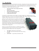
1.1 - Introduction CR2 is a revolutionary bar code and 2-dimensional code reader. Developed to be the first universal reader, no other single device performs as many functions. With a cost of ownership far less than comparable systems, the CR2 incorporates a unique dual path optical system, a 1.3 million pixel CMOS sensor, and a 400 MHz processor.
1.2 - Unpacking Remove the imager from its packing and inspect it for damage. If the scanner was damaged during shipping, please call Code at (801) 495-2200. The standard CR2 unit is shipped with a USB cable interface. The unit also features a battery blank which must be installed when using the reader (except when attached to the H2, BH1 or BH2 handle). Various accessories are available for the CR2. • 4 cable options (USB 6ft., USB 12 ft.
1.3 - Reader Battery Installation Attaching and Detaching the Lithium Ion Battery The CR2 has an option to include a 1950 mAH Lithium Ion battery. To install battery, make sure the battery is in the correct position (figure 1.1). Place the plastic tab of the battery into the reader (figure 1.2). Push the battery in and slide the locking mechanism down (figures 1.
1.4 - Attaching Handles H1 - Handle 1. Place the CR2 in the cradle of the handle and slide the unit back (Figure 1.4). Be careful not to place fingerprints on the front glass when attaching handle. 2. Once the 8-pin DIN connector of the handle begins to enter the opening in the back of the unit, firmly press the unit back until the unit is flush against the handle (Figure 1.5). Figure 1.4 Figure 1.5 H2 - Ruggedized Cabled Handle 1. Make sure the reader has no battery or battery blank installed. 2.
1.5 - Batch Operation 1.5.1 - Introduction The CR2 unit features a batch mode for applications requiring a portable reader. Batch mode allows a user to store scanned data to the reader’s non-volatile memory. The user may transfer the data to a host computer when needed. To utilize batch functionality you will need to purchase the 1950 mAH Lithium Ion battery from a Code representative. The CR2 may be programmed to operate in three different batch modes: 1.
Transferring and Deleting Data There are three different codes to transfer and delete data in memory. 1. Transfer All Data in Memory - This code will send all data in memory everytime the code is scanned. 2. Transfer Only Unsent Data in Memory - This code will send only the data in memory that hasn’t already been sent when the code is scanned (ONLY works in Send & Buffer and Send & Log modes). 3.
1.6 - Cabled Operation 1.6.1- Introduction The CR2 is a Multi-Interface Unit (MIU) and is available with USB (6 ft. or 12 ft.), RS-232 (Serial) and PS/2 cables (Figure 1.9). All of the cables are connected to the CR2 with a 8-pin DIN connector. Figure 1.9 Hand Held CR2 - To install a cable directly to the CR2, correctly line up the 8-pin DIN connector into the back end of the reader. The arrows on the connector should be facing down (Figure 1.10).
1.6.2 - CR2 as a USB Keyboard To connect the CR2 to your host computer via USB interface: 1. Attach the USB cable to CR2 (Figure 1.14). 2. There is no need to power off the computer (Figure 1.15) Connect the USB cable to a USB port on the computer (Figure 1.16). 3. Once properly connected, the CR2 will power on and beep. 4. Scan the below code (M049_03) for USB Keyboard Mode: USB Keyboard Factory Reset Save Settings 5. Scan the Save Settings Code (M188_02) Figure 1.
1.6.2.1 - Addional USB Communication Settings USB Keyboard Mode - Data is sent from the Reader and interpreted by the host just as if a USB keyboard was being used to enter data. USB Downloader - This mode is used when downloading firmware. USB Native Two Way Mode - This mode is utilized when there is a need for error-corrected communication between the CR2 and an application through the USB port. USB Virtual COM 1 Way Mode - This mode allows a USB-cabled CR2 to function as a virtual COM port.
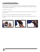
1.6.3 - PS/2 Cable Installation Guide 1. Power off the computer. If you disconnect the computer’s keyboard while it is powered on, your computer will lock up. 2. Attach the the PS/2 cable to the CR2. 3. If you have a cabled keyboard, detach the keyboard cable from the computer and connect that same connector to the female connection on the CR2 PS/2 cable (Figure 1.17). 4. Now connect the male CR2 PS/2 connector into the keyboard port on the computer (Figure 1.18). 5. Power on the computer.
1.6.4 - RS-232 (Serial) Cable Installation Guide 1. Attach the RS-232 (Serial) Cable to the CR2. 2. Connect the RS-232 (Serial) cable to a serial port on the computer (Figure 1.19). There is no need to power off the computer. 3. The RS-232 (Serial) interface has an optional 5V/1.5A power supply (Figure 1.20). If you have a power supply, plug the power supply adapter into the RS-232 (Serial) cable and then plug the power adapter into a wall socket (Figure 1.21). Figure 1.19 Figure 1.20 Figure 1.21 4.
1.6.4.1 - Additional RS-232 (Serial) Communication Data Bit Settings Scan the following codes to set the appropriate data bit: 7 Data Bits 8 Data Bits (Default) 1.6.4.2 - Additional RS-232 (Serial) Communication Baud Rate Settings Scan the following codes to set the appropriate baud rate: 1200 2400 4800 9600 19200 38400 57600 (Default) 115200 1.6.4.
1.7 - Bluetooth Radio Operation 1.7.1 - Introduction The CR2 features a Bluetooth® wireless radio. The radio allows for point-to-point wireless communication with other Bluetooth devices that support serial port protocol (SPP). If keyboard entry is necessary, Code XML Router will need to be installed. The following guide will give you general instructions on connecting your CR2 to a desktop or laptop computer with a Bluetooth radio.
1.7 - Bluetooth Radio Operation (continued) Radio Range and Transferring Data The CR2 radio is a Class 1 device. If connected to another Class 1 device the reader has roughly a 100 meter (300 feet) line of sight operating range. If connecting to a Class 2 or Class 3 device, the operating range may drop to match the lower range. Once a reader is connected, a serial application must be opened (HyperTerminal) unless Code XML Router is installed.
1.7 - Bluetooth Radio Operation (continued) Permanently Establishing a Connection Scan the Save Settings Code at the bottom of the page to make the RF settings (including which device to connect to) permanent on the reader: Disconnecting from the Device You may force disconnection by reading the disconnect code below (The CR2 may not appear disconnected in the slave Bluetooth connection manager for 10 – 15 seconds after the command is issued).
1.7.4 - Bluetooth Radio Time Out Settings Scan the following codes to set the period of time before the Bluetooth Radio will go into sleep mode due to inactivity: Note: Increasing the time before the reader will time out will decrease battery life. 90 Seconds (Default) 5 Minutes 10 Minutes 30 Minutes 1 Hour 2 Hours 15 Minutes 1.7.
1.7.7 - Configuration for Belkin Bluetooth Manager Software (Version 1.4.2.10) In this version of the Belkin Bluetooth Manager software, you must disable the authentication feature to connect a CR2. Follow the steps below: 1. Double click on the Bluetooth icon in the system tray. In the My Bluetooth Places Screen, select Advanced Configuration. 2. Select the Local Services tab and double click on the Bluetooth Serial Port. Inder the General tab unselect the Secure Connection box.
1.7.7 - Configuration for Belkin Bluetooth Manager Software (Continued) 3. 4. Your local service Bluetooth Serial Port profile should now read “Not Required” Open the “Accessibility” Tab and verify that “All Devices” are allowed to connect (this is the default setting). You should now be able to connect your CR2.
1.7.8 - Configuration for Toshiba Bluetooth Stack Instructions (continued) 3a. Go to http://www.codecorp.com/bdaddr.php and create a QuickConnect code using the address from step 3. Use the CodeXML Router/ 2-way applications section if CodeXML Router will be installed. Else create a QuickConnect Code using the section for Serial Applications. 4. Optional – To remove the Passkey dialogue when connecting, Select the Security TAB and Select Custom Level.
1.7.8 - Configuration for Toshiba Bluetooth Stack Instructions (continued) 4a. Uncheck the settings under the Security Setting of Serial Port (SPP). 5. Install the Code XML Router Software to the Device on the Appropriate COM Port. Reboot the PC and then scan your QuickConnect code to connect. Please note that the Toshiba Stack does not allow a device to connect until the Com Port is opened.
1.7.9 - Configuration for Microsoft Bluetooth Stack Instructions 1. Right click on the Microsoft Bluetooth Stack system tray icon, select “Open Bluetooth Settings”. 2. Go to the “Hardware” tab and select the “Generic Bluetooth Radio” and then click “Properties”. Next select the “Advanced” tab. Note the Address. For the example show below it is 00:17:9a:2b:69:bb.
1.7.9 - Configuration for Microsoft Bluetooth Stack Instructions (continued) 2a. Go to http://www.codecorp.com/bdaddr.php and create a QuickConnect code using the address from step 2. Use the CodeXML Router/ 2-way applications section if CodeXML Router will be installed, otherwise create a QuickConnect Code using the section for Serial Applications. 3. Under “COM Ports” tab, select “Add”. In Add COM Port dialog box, select Incoming, click OK.
1.7.10 - Installing CodeXML Router Bluetooth Edition for Windows 1. Insert the Code Router Bluetooth Edition for Windows CD into your PC’s CD drive. The CD will automatically begin the installation process. When you get to the screen pictured below, please enter the CD Serial # Key found on the card included in the CD case. 2. When you get to the screen pictured below, please choose from the appropriate settings. For a description of each setting, please see Chapter 3.
1.8 - CR2 Feedback Guide The CR2 features two (2) LED’s on the front of the unit. These LED’s give feedback based on various funcitons of the CR2 unit. Each LED has a small icon just underneath it that represents the following: Memory / Connection Icon Battery or Power Icon The CR2 unit will automatically flash battery or power status every 15 seconds. Each LED can show three (3) colors; Green, Amber, or Red. The colors will vary depending on the message the unit is sending.
Normal Operation Feedback (con’t) Memory/Connection LED Battery LED Sound Successful Decode and Data Transfer via cable None Solid Green 1 Beep Successful Decode and Data Store Memory Status None 1 Beep Batch Mode memory full Solid Red None 3 Beeps Configuration Code Successfully Decoded and Processed None None 1 Beep slight pause then 1 Beep Configuration Code Successfully Decoded But Was Not Successfully Processed None None 6 Beeps Bluetooth Radio Feedback Memory/Connection LED Att
1.9 - Targeting and Reading Techniques The CR2 utilizes digital camera technology to take a picture of a symbol. Once an image is captured, the CR2 utilizes advanced decoding algorithms to extract data from the captured image. The CR2 is available as a palm-held unit or users may purchase a handle (available in various types). The palm held unit features left and right triggers. These triggers may be programmed to perform various features.
1.10 - Imager Field of View and Resolution The CR2’s dual field optical system may be modified based on your scanning environment. The CR2’s megapixel imager may be set to the following three modes: The 1.3 Million Pixel imager is divided into near field and far field decode zones. In each zone the resolution is 1024 x 640 pixels (see Figure 1.25). In this mode of operation the reader utilizes the highest resolution creating the widest working range on bar code and 2-dimensional symbols of all densities.
1.11 - Decode Zone Figure 1.
Chapter 2 - Optimization and Trigger Programming Save Settings C001537_18_CR2_User_Manual 30
2.1 - Introduction From the moment you turn on your CR2, you are taking full advantage of the dual path 1.3 megapixel imager, the 400 MHz processor. CR2 readers are able to read a wide range of symbology types and sizes, as well as a variety of printed media, within a wide range of environmental factors including light (natural or ambient lighting). By defining if you are scanning large, small, high denisty or low density types of symbology(s), the CR2 has options that will maximize decoding speed.
2.2 - Global Trigger Optimization Matrix SXGA Both Fields Near Field Far Field 2.
2.4 - Left Trigger Programming Left Trigger Take Picture Note: If you program a trigger to another function, you will need to reset any performance code settings. 2.5 - Right Trigger Optimization Matrix SXGA Both Fields Near Field Far Field 2.6 - Right Trigger Programming Right Trigger Take Picture Note: If you program a trigger to another function, you will need to reset any performance code settings.
2.7 - Handle Optimization Matrix SXGA Both Fields Near Field Far Field 2.8 - Handle Trigger Programming Handle Trigger Take Picture Note: If you program a trigger to another function, you will need to reset any performance code settings.
2.9 - Continuous Trigger Optimization Matrix Scanning codes in the matrix puts the reader into Continous scan. SXGA Both Fields Near Field Far Field 2.10 - Continuous Scan Off (Default) On Note: This function is only recommended for cabled or short term use if battery is the only power supply. See section 2.11.1 for Sleep Time Out Settings.
2.11 - Continuous Scan Settings 2.11.
Chapter 3 - CR2 Programming: Symbology Settings Save Settings C001537_18_CR2_User_Manual 37
3.1 - Aztec Symbology Scan the following codes to enable/disable Aztec symbology settings: Aztec On Aztec Off (Default) Sample Aztec Code 3.2 - Codabar Symbology Scan the following codes to enable/disable Codabar symbology settings: Codabar On (Default) Codabar Off Sample Codabar 3.
3.5 - Code 39 Symbology Scan the following codes to enable/disable Code 39 symbology settings: Code 39 On (Default) Code 39 Off Enable Checksum Disable Checksum (Default) Enable Checksum and Strip From Result Code 39 Extended Full ASCII On Code 39 Extended Full ASCII Off (Default) Code 39 Short Margin On Code 39 Short Margin Off (Default) Code 39 Trioptic On Code 39 Trioptic Off Sample Code 39 Code Sample Trioptic Code 39 3.
3.7 - Code 128 Symbology Scan the following codes to enable/disable Code 128 symbology settings: Code 128 On (Default) Code 128 Off Code 128 Short Margin On Code 128 Short Margin Off (Default) Sample Code 128 Code Note: When Codablock F and Code 128 decoding are enabled, there is some danger of mistakenly decoding a damaged Codablock F symbol as a Code 128 symbol. Therefore, Code 128 decoding should be disabled when Codablock F decoding is enabled. 3.
3.10 - GoCode Symbology GoCode is a miniature, two-dimensional (2-D) symbol. Developed to fit within a line of text, GoCode features a multidimensional, adaptable matrix pattern that may be reproduced on virtually any surface. GoCode is a private symbology and may be utilized by purchasing a runtime license through Code. GoCode has many significant advantages over all common linear barcodes and 2-D symbols. Please contact Code for more information on the benefits of utilizing a private symbology.
3.13 - Matrix 2 of 5 Symbology Scan the following codes to enable/disable Matrix 2 of 5 symbology settings: Matrix 2 of 5 On (Default) Matrix 2 of 5 Off Matrix 2 of 5 Sample 3.14 - Micro PDF417 Symbology Scan the following codes to enable/disable micro PDF 417 symbology settings: MicroPDF417 On MicroPDF417 Off (Default) Sample MicroPDF417 3.
3.18 - PDF 417 Symbology Scan the following codes to enable/disable PDF 417 symbology settings: PDF 417 On (Default) PDF417 Off Macro PDF 417 Off (Default) Sample PDF 417 Code Macro PDF 417 On 3.19 - Pharmacode For an explanation of Pharmacode settings and all programming codes please refer to Appendix G of the CR2 User Manual. You may download the Appendix G at: http://www.codecorp.com/manuals.html 3.20 - Postal Symbologies All postal code default settings are OFF.
3.21 - QR Code Symbology Scan the following codes to enable/disable QR Code symbology settings: QR Code On QR Code Off (Default) Enable Checksum Disable Checksum (Default) QR Code Inverse On Both Inverse and Standard On All QR On (includes Micro QR) Inverse QR and Micro QR On Sample QR Code Sample Micro QR 3.
3.23 - Telepen Symbology Scan the following codes to enable/disable Telepen symbology settings: Telepen On - Default Telepen Off Sample Telepen 3.
Chapter 4 - Reader Feedback and Special Settings Save Settings C001537_18_CR2_User_Manual 46
4.1 - Volume and Vibration Settings Scan the following codes to set vibration mode: Vibrate On / Beep On Vibrate On / Beep Off Vibrate Off / Beep On (Default) Scan the following codes to set your reader’s volume: Beep Off Beep Low Beep High (Default) 4.2 - Code Readability Index The Readability Index provides a measurement of a specific symbol’s ease or difficulty to be decoded by the CR2.
4.3 - Laser Settings Scan the following codes to turn laser targeting on/off: On (Default) Off Scan one of the following codes to set the brightness of the CR2 laser. High (Default) Medium Low 4.
4.5 - Reader ID and Firmware Version To find out the Reader ID and firmware version, open a text editor program (i.e., Notepad, Microsoft Word, etc.
4.7 - Lock-out Link Mode This mode can be used to establish a permanent connection between the reader and a CodeXML modem, Prepare the reader to communicate in ‘RF Comm Mode’ by scanning the QuickConnect code on the paired modem to which you wish to establish a permanent link. Listen for the single beep to verify the connection acknowledgement. Scan the Lockout Link Mode code (see below). Set appropriate timeout settings, if applicable (see Section 1.6.5).
Chapter 5 - Advanced Decode Performance Save Settings C001537_18_CR2_User_Manual 51
5.1 - Set Targeting Tolerances The targeting tolerance is the zone around the laser which is eligible for decoding. The values of each of the following codes are the percent tolerance based on the size of the barcode. As the targeting tolerance becomes smaller the targeting laser must be more centered in the symbol being read. Conversely, as the targeting tolerance gets larger there is less precision needed with the targeting laser.
5.2 - Windowing If only one size of bar code is being scanned in an application, the CR2 can be optimized to reduce processing time by adjusting the viewing area within the field of view of the image. By reducing the vertical window value of the imager to 200 pixels, 1D codes are processed more quickly. Because only a horizontal strip of a 1D code is needed to be decoded, using a narrow strip of the imager is all that is needed.
Users may optimize the CR2 decode zone if their application only requires one bar code format. If the size and density of the bar codes to be scanned are consistent, please select the setting below that best describes your environment. 1-Dimensional Codes ONLY (1024 x 200 pixels) Caution: It may be more difficult to read other codes while in this setting. You must have the reader farther away than normal.
Chapter 6 - Adding a Prefix or Suffix and Reader Text Commands Save Settings C001537_18_CR2_User_Manual 55
6.1 - Prefix Settings If you scan the following codes, you will lose any unsaved settings. Make sure to save settings on your reader before scanning the prefix codes. If you scan more than one prefix you will receive each scanned prefix in your scanned data; (i.e., if you scan comma prefix twice, you will get two comma prefixes).
6.3 - Erase Prefix and Suffix Settings Scan the following codes to erase all prefix and suffix data. Erase Prefix & Suffix Data 6.4 - Reader Text Commands Enabling Reader Text Commands allows the CR2 to accept text commands via RS-232 or RF commmunication. Scan the following codes to enable/disable reader text commands: Reader Text Commands On Reader Text Commands Off - Default Note: Text commands can only be sent to the reader when it is active.
Chapter 7 - CR2: Maintenance and Troubleshooting Save Settings C001537_18_CR2_User_Manual 58
7.1 - Reset Reader to Factory Defaults Scan the following codes to reset reader: Reset to USB Factory Default Settings Reset to PS/2 Factory Default Settings Reset to RF One Way Factory Default Settings Bootloader Mode Clear All CodeXML Rules Prefix & Suffix Reset to RS-232 Factory Default Settings Bootloader mode is utilized to download new version of bootloader firmware. Clear All Stored Data Save Settings 7.
7.3 - Warranty Code Corporation’s Code Reader 2.0 carries a three year limited warranty as described herein. Customers may purchase a one or two year extension to this warranty. Please contact a Code representative for more information. Limited Warranty Code manufactures its hardware products in accordance with industry-standard practices.
EXCEPT FOR THE WARRANTIES STATED ABOVE, CODE DISCLAIMS ALL WARRANTIES, EXPRESS OR IMPLIED, ON PRODUCTS FURNISHED HEREUNDER, INCLUDING WITHOUT LIMITATION IMPLIED WARRANTIES OF MERCHANTABILITY AND FITNESS FOR A PARTICULAR PURPOSE AND NON-INFRINGEMENT. The stated express warranties are in lieu of all obligations or liabilities on part of Code for damages, including without limitation, special, indirect, or consequential damages arising out of or in connection with the use or performance of the product.