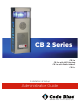
CB 2 Series CB 2-e CB 2-e with AED Housing CB 2-e with Public Address CB 2-s Installation & Setup Administrator Guide 800.205.7186 • www.codeblue.
CB 2 Series Administrator Guide Table of Contents Section Page 2 Introduction....................................................................................3 3 Getting Started...............................................................................4 3.1 CB 2-e Replacement Parts List............................................5 3.2 CB 2-e with Public Address Replacement Parts List............6 3.3 Cb 2-e with AED Housing Replacement Parts List...............7 3.
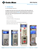
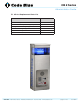
CB 2 Series Administrator Guide 2 Introduction The 2 Series Wall Mount Help Points This popular line is a good fit for any indoor or outdoor application including parking facilities. Our unmistakable craftsmanship makes our Help Points® the most rugged on the market, withstanding the punishment of natural and man-made disasters. With durable construction, our wall mount units can meet any requirement or purpose.
CB 2 Series Administrator Guide 3 Getting Started Basic Install Instructions 1. EIA/TIA, ANSI, CSA and BICSI cabling or similar standards shall be adhered to for proper operation of Code Blue communication devices connected to copper or fiber infrastructures. Communications cable and electrical cable in the same conduit is not an acceptable installation and shall not be supported. Analog phones require a minimum of 23mA for proper operation (26-29mA recommended). 2.
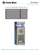
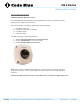
CB 2 Series Administrator Guide 3.1 CB 2-e Replacement Parts List Part Part Number LED Strobe Light 40159 Button Head Security Screws (3 pack) 41418 Analog Phone Line Surge Suppressor 41471 IP Phone Line Surge Suppressor 41421 Manifold R/B 5-way 40101 Power Brick 120V, 240V, 277V, & 347V 40104 CB 2-e Code Blue • 259 Hedcor Street • Holland, MI 49423 USA • 800.205.7186 • www.codeblue.
CB 2 Series Administrator Guide 3.2 CB 2-e with Public Address Replacement Parts List Part Part Number LED Strobe Light 40159 Button Head Security Screws (3 pack) 41418 Analog Phone Line Surge Suppressor 41471 IP Phone Line Surge Suppressor 41421 Manifold R/B 5-way 40101 PAS AMP Kit 24V 40009 Power Brick 120V, 240V, 277V, & 347V 40104 PAS Speaker 40080 CB 2-e with Public Address Code Blue • 259 Hedcor Street • Holland, MI 49423 USA • 800.205.7186 • www.codeblue.
CB 2 Series Administrator Guide 3.
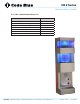
CB 2 Series Administrator Guide 3.4 CB 2-s Replacement Parts List Part Part Number LED Strobe Light 40159 Button Head Security Screws (3 pack) 41418 Analog Phone Line Surge Suppressor 41471 IP Phone Line Surge Suppressor 41421 Manifold R/B 5-way 40101 Power Brick 120V, 240V, 277V, & 347V 40104 LED Area Light 41539 CB 2-s Code Blue • 259 Hedcor Street • Holland, MI 49423 USA • 800.205.7186 • www.codeblue.
CB 2 Series Administrator Guide 4 Installation Instructions 4.1 CB 2-e Installation Instructions Pre-Installation Electrical preparation – The unit may have supply wires run either behind the unit through the wall or below the unit by using an external conduit through the bottom of the unit. Holes in the back and the bottom of the unit have been provided for this purpose. Installation Procedures 1. Remove the top of the unit. 2.
CB 2 Series Administrator Guide CB 2-e Additional Options HIKVISION Network Mini Dome Camera The HIKVISION Mini Dome Network IP Camera installed in this unit is a Code Blue 3rd Party Partner product. Model # DS-2CD7153-E. The network camera is set with the following factory default settings: 1. 2. 3. 4. IP Address: 192.0.0.64 Camera is accessed on IP Port 8000 User Name: admin Password: 12345 For additional support, contact HIKVISION at: 1. Website: http://www.hikvision-usa.com/support.html 2.
CB 2 Series Administrator Guide CB 2-e Installation Instructions (continued) Code Blue • 259 Hedcor Street • Holland, MI 49423 USA • 800.205.7186 • www.codeblue.
CB 2 Series Administrator Guide CB 2-e Installation Instructions (continued) Suggested installation dimensions shown from ground to lower right mounting hole are for single button faceplates. • For dual button faceplate, deduct 3.25 inches. • For keypad faceplate, deduct 4.5 inches. • For wheelchair direct facing access only, deduct 6 inches. DISCLAIMER: The dimensions above are intended as guidelines only. For specific installation requirements reference your local codes.
CB 2 Series Administrator Guide 4.2 CB 2-e with Public Address Installation Instructions Pre-Installation Electrical preparation – The unit may have supply wires run either behind the unit through the wall or below the unit by using an external conduit through the bottom of the unit. Holes in the back and the bottom of the unit have been provided for this purpose. Installation Procedures 1. Remove the top of the unit. 2.
CB 2 Series Administrator Guide CB 2-e with Public Address Installation Instructions (continued) Code Blue • 259 Hedcor Street • Holland, MI 49423 USA • 800.205.7186 • www.codeblue.
CB 2 Series Administrator Guide CB 2-e with Public Address Installation Instructions (continued) Suggested installation dimensions shown from ground to lower right mounting hole are for single button faceplates. • For dual button faceplate, deduct 3.25 inches. • For keypad faceplate, deduct 4.5 inches. • For wheelchair direct facing access only, deduct 6 inches. DISCLAIMER: The dimensions above are intended as guidelines only. For specific installation requirements reference your local codes.
CB 2 Series Administrator Guide 4.3 CB 2-e with AED Housing Installation Instructions Pre-Installation Electrical preparation – The unit may have supply wires run either behind the unit through the wall or below the unit by using an external conduit through the bottom of the unit. Holes in the back and bottom of the unit have been provided for this purpose. Installation Procedures 1. Remove the top of the unit. 2.
CB 2 Series Administrator Guide CB 2-e with AED Housing Installation Instructions (continued) 12.53 8.00 36.00 46.72 21.00 23.06 3.00 15.5 9.00 11 Code Blue • 259 Hedcor Street • Holland, MI 49423 USA • 800.205.7186 • www.codeblue.
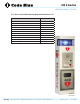
CB 2 Series Administrator Guide CB 2-e with AED Housing Installation Instructions (continued) Ø .44 MOUNTING HOLES 4 PLCS 45.22 36.00 Ø 1.13 KNOCKOUTS FOR Ø 3/4 CONDUIT 2 PLCS 8.00 21.00 3.00 BOTTOM 9.00 12.40 28.00 GROUND LEVEL 2.20 REF 8.00 1.62 MOUNTING SURFACE Ø 1.13 THRU BOTTOM PLATE FOR Ø 3/4 CONDUIT 2 PLCS Suggested installation dimensions shown from ground to lower right mounting hole are for single button faceplates. • For dual button faceplate, deduct 3.25 inches.
CB 2 Series Administrator Guide 4.4 CB 2-s Installation Instructions Pre-Installation Electrical preparation – The unit may have supply wires run either behind the unit through the wall or below the unit by using an external conduit through the bottom of the unit. Holes in the back and the bottom of the unit have been provided for this purpose. Installation Procedures 1. Remove the light bracket and outer shell from the back plate. 2.
CB 2 Series Administrator Guide CB 2-s Installation Instructions (continued) Code Blue • 259 Hedcor Street • Holland, MI 49423 USA • 800.205.7186 • www.codeblue.
CB 2 Series Administrator Guide CB 2-s Installation Instructions (continued) 12 REF 4 X Ø7/16 MOUNTING HOLES 30 3/4 42 REF 2 X Ø1-1/8 (KNOCKOUTS FOR Ø3/4 CONDUIT) 2 9/16 8 5/16 REF 1 1/2 REF 6 1 1/2 9 43 GROUND/FLOOR Suggested installation dimensions shown from ground to lower right mounting hole are for single button faceplates. • For dual button faceplate, deduct 3.25 inches. • For keypad faceplate, deduct 4.5 inches. • For wheelchair direct facing access only, deduct 6 inches.
CB 2 Series Administrator Guide 4.5 Pole Mount Bracket Installation Instructions 1. Thread the mounting straps through the slots; use the outside slots for larger poles and inside slots for smaller poles. 2. Hold bracket to pole; Set the height of the bracket (C) so the speakerphone push button(s) on the unit will be at desired height (please check with local codes for ADA compliance). 3. Band the bracket to the pole at desired height. To eliminate waste, pull band (A) from carton as needed.
CB 2 Series Administrator Guide 5 Wiring Diagrams 5.1 CB 2-e Wiring Diagram Product wiring diagram shown reasonably represents current offering and is intended to assist in component identification and service. Earlier product production may have different components and wiring connections. Reference the model and serial number from the unit ID tag and contact manufacturer to confirm replacement part version and availability. Code Blue • 259 Hedcor Street • Holland, MI 49423 USA • 800.205.7186 • www.
CB 2 Series Administrator Guide PAS 2-e Wiring Diagram 5.
CB 2 Series Administrator Guide 5.3 CB 2-e with AED Housing Wiring Diagram AED Housing AED Housing Product wiring diagram shown reasonably represents current offering and is intended to assist in component identification and service. Earlier product production may have different components and wiring connections. Reference the model and serial number from the unit ID tag and contact manufacturer to confirm replacement part version and availability.
CB 2 Series Administrator Guide 5.4 CB 2-s Wiring Diagram Product wiring diagram shown reasonably represents current offering and is intended to assist in component identification and service. Earlier product production may have different components and wiring connections. Reference the model and serial number from the unit ID tag and contact manufacturer to confirm replacement part version and availability. Code Blue • 259 Hedcor Street • Holland, MI 49423 USA • 800.205.7186 • www.codeblue.
CB 2 Series Administrator Guide 5.5 CB 2-e and CB 2-s PoE Wiring Diagram Product wiring diagram shown reasonably represents current offering and is intended to assist in component identification and service. Earlier product production may have different components and wiring connections. Reference the model and serial number from the unit ID tag and contact manufacturer to confirm replacement part version and availability. Code Blue • 259 Hedcor Street • Holland, MI 49423 USA • 800.205.7186 • www.
CB 2 Series Administrator Guide Maintenance Schedule 6 Maintenance Schedule Guidelines LEGEND G Guard tasks T Technician tasks DAILY OR WEEKLY G Perform functional communications check Action: Press red button Strobe activates Red LED “Call Placed” light turns on Message plays Call connects, green LED “Call Received” light turns on Confirm conversation clarity with dispatch MONTHLY OR QUARTERLY G Visually check lighting functions: Faceplate light Beacon G Visually inspect unit for
CB 2 Series Administrator Guide Maintenance Schedule Maintenance Schedule (continued) Guidelines UNIT SURFACE MAINTENANCE The painted and stainless steel Code Blue models require periodic care to sustain their aesthetic appearance. Units located outdoors are vulnerable to harsh environmental conditions, including UV rays, acid rain, diesel fumes and airborn iron particles (i.e., dust) which over time may cause unit discoloring.
CB 2 Series Administrator Guide 6.1 CB 2-e with AED Access and Maintenance The following methods can be used to access the Automated External Defibrillator (AED) device: 1. When the red button is depressed the unit will make a call. After the call has been answered, the answering party can then depress the 6 key on their telephone keypad. This will release the door latch, giving the caller access to the AED device. 2. The units have a key fob supplied at the time of purchase.
CB 2 Series Administrator Guide 7 Locating Unit Serial Numbers Remove the speakerphone faceplate with the special security bit. The serial number will be listed on the manufacturer’s label located inside the unit (1). 1 Code Blue • 259 Hedcor Street • Holland, MI 49423 USA • 800.205.7186 • www.codeblue.
CB 2 Series Administrator Guide 8 Warranty Code Blue Corporation provides a limited warranty on this product. Refer to your sales agreement to establish the terms of the limited warranty. In addition, Code Blue’s standard warranty language as well as information regarding support for this product, while under warranty, is available through the following website: www.codeblue.com. Code Blue • 259 Hedcor Street • Holland, MI 49423 USA • 800.205.7186 • www.codeblue.
CB 2 Series Administrator Guide 9 Download Information Download Information Main Location: http://codeblue.com/support/downloads/ Code Blue now has a centralized location where you can find all the Installation, Setup, Information, Configuration & Operation instructions. 1. IA4100 Installation & Setup: http://codeblue.com/resources/admin-guides/ 2. IA4100 Configuration & Operation: http://codeblue.com/resources/user-guides/ 3. IP5000 Installation & Setup: http://codeblue.com/resources/admin-guides/ 4.