PROFESSIONAL SERIES Security and Keyless Entry Installation Guide ca1153 2012 Audiovox Electronics Corporation. All rights reserved.
Table of Contents Before You Begin ...................................................................................... 3 Wire Connection Guide ........................................................................... 4 6 Pin Main Harness ................................................................................... 5 6 Pin Input / Output Harness .................................................................... 6 3 Pin AUX Output Harness .........................................................
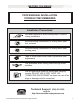
BEFORE YOU BEGIN PROFESSIONAL INSTALLATION STRONGLY RECOMMENDED Installation Precautions: Roll down window to avoid locking keys in vehicle during installation Avoid mounting components or routing wires near hot surfaces Avoid mounting components or routing wires near moving parts Tape or loom wires under hood for protection and appearance Use grommets when routing wires through metal surfaces Use a Digital Multi Meter for testing and verifying circuits.
6 Pin Main Harness 6 Pin Input / Output Harness 3 Pin AUX Output Harness 6 Pin Door Lock Output Harness 4 ca1153 rev A.
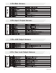
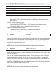
6 Pin Main Harness 1 WHITE PARKING LIGHT OUTPUT 2 WHITE/RED PARKING LIGHT INPUT 3 WHITE PARKING LIGHT OUTPUT Locate the parking light output wire at the vehicle’s light switch. Verification: This wire registers positive voltage when the parking lights are turned on. Positive switching Parking Lights: Connect the WHITE/RED wire to a 15 Amp max fused battery source. Connect the WHITE wire to the parking light output wire.
RED BATTERY 12V ( + ) Locate 1 of the vehicle’s constant 12 Volt battery wires at the ignition switch. Verification: This wire will register ( + ) voltage in all positions of the ignition switch. Connect the RED wire to the constant 12 Volt battery wire. NOTE: Remove all fuses until all connections are made. 6 Pin Input / Output Harness 1 PURPLE DOOR TRIGGER INPUT ( + ) Locate the vehicle’s dome light or door pin switch wire.
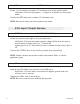
3 GREEN DOOR TRIGGER INPUT ( - ) Locate the vehicle’s dome light or door pin switch wire. Verification: This wire will register ground (NEG) when the door is opened and the interior light is on. This wire will register positive voltage when the door is closed and the interior light is off. Connect the GREEN wire to the vehicle’s negative door input wire(s). NOTE: Certain vehicles may require multiple connections.
3 Pin AUX Output Harness 1 VIOLET/BLACK AUX 1 OUTPUT ( - ) This wire provides a ( - ) 300mA output capable of driving relays. For Control of optional accessories (i.e. Power Window/Sunroof, etc.). To activate refer to the transmitter button configuration chart. Please refer to the selectable options for timing. 2 GREEN/BLACK FACTORY DISARM ( - ) This wire will supply a ( - ) 300mA pulse both upon disarming the system and when the trunk release feature is activated.
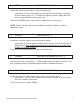
6 Pin Door Lock Output Harness 1 BROWN/BLACK UNLOCK SWITCH ( 87A ) 2 BLUE/BLACK UNLOCK MOTOR ( 30 ) 3 VIOLET/BLACK UNLOCK POLARITY ( 87 ) 4 WHITE/BLACK LOCK SWITCH ( 87A ) 5 GREEN/BLACK LOCK MOTOR ( 30 ) 6 VIOLET LOCK POLARITY ( 87 ) The door lock / unlock outputs are designed to control several different types of systems which may require additional parts.
Additional Ports LED Port The LED included in the kit will serve as a visual indicator of the alarm’s status. It should be installed in the dash, located where it can be easily seen from outside the vehicle, yet not be distracting to the driver. Once a location has been selected, check behind the panel for wire routing access, and to confirm the drill will not damage any existing components as it passes through the panel.
Set Up & Programming Transmitter Programming - Feature Bank 1 1. Turn the ignition ON. 2. Press and hold the valet/override button. 3. Within 10 seconds the system will chirp (3) three times. 4. Press 1 button of each transmitter you wish to program. 5. The system will respond with 1 chirp for each accepted transmitter. 6. Pressing the override button at anytime during programming will advance to the next bank. NOTE: The system will exit transmitter programming after 15 seconds of inactivity.
button anytime while in any of the Defaulting All Features: Pressing the feature banks will default all features and return you to feature bank 2 - 4 chirps. NOTE: The system will remain in feature programming mode as long as the ignition is on, there is no time limit. To exit programming turn the IGNITION OFF. Feature Bank 1 - 3 Chirps Transmitter Programming Refer to transmitter programming.
Feature Bank 3 - 5 Chirps Output Control 1 LED Flash 2 LED Flash 3 LED Flash 4 LED Flash 5 LED Flash 1 Extended Lock Pulse 1 Second 3.
Dome Light Delay / Theater Dimming The system can be programed to delay arming after the lock button is pressed (60 second max) for vehicles with a dome light delay or theater dimming feature. Once programed the system will ‘learn’ the timing of the dome light delay and add 2 seconds before arming. 1. Close all doors with ignition off. 2. Using the transmitter press LOCK, UNLOCK, LOCK ,UNLOCK, LOCK , UNLOCK, LOCK. The LED will light solid to indicate the system has entered DOME DELAY LEARN MODE. 3.
4 - Siren / Horn: This feature selects which output(s) will sound the system’s arm/disarm chirps. This feature does not effect the triggered state of the security system and during a triggered cycle, both the siren and horn outputs will activate respectively. 5 - Siren Duration: Determines the length of time the system will sound the siren/horn during a full trigger event. 6 - Security: Controls security functionality - ON / OFF. ON - Full security functionality. OFF - The security system does not trigger.
Feature Bank 3 - Output Control 1 - Extended Lock Pulse: Controls the timing of the BLUE and GREEN lock output wires. 1 Second - Single 1 second lock pulse, single 1 second unlock pulse. 3.5 Seconds - Single 3.5 second lock pulse, single 3.5 second unlock pulse. 1 Second Lock, Double Pulse Unlock - Single 1 second lock pulse, double 1 second unlock pulse. 30 Second Lock, Double Pulse Unlock - Single 30 second lock pulse, double 1 second unlock pulse.
5 - Horn Output Timing: Control the minimum horn pulse time in milli seconds, some vehicle will require a longer pulse to activate the factory horn. 16mS 10mS 30mS 40mS 50mS 6 - Real Panic: Controls the panic out when triggered from the transmitter. ON - Randomized horn honks when panic is triggered. OFF - Standard pattern horn honks when panic is triggered. 7 - AUX 1 - Violet/Black Output: Controls the VIOLET/BLACK AUX 1 output activation type and timing.
Security Trigger Zones If the security system has been triggered the LED will flash one of the patterns below indicating the zone. LED FLASHES TRIGGER ZONE 18 2 Flashes Hood / Trunk Input 3 Flashes Door Input 4 Flashes Shock Sensor 5 Flashes Ignition Input ca1153 rev A.
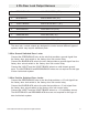
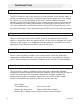
STARTER INTERUPT RELAY 87 86 87a 30 85 ORANGE RED BLACK WHITE / BLACK OPEN 2012 Audiovox Electronics Corporation. All rights reserved.
Audiovox Electronics Corporation. Customer Service 1-800-421-3209 WWW.CODE-ALARM.COM FCC COMPLIANCE This device complies with Part 15 of the FCC rules and with RSS-210 of Industry Canada. Operation is subject to the following two conditions: 1. This device may not cause harmful interference, and 2. This device must accept any interference received, including any interference that may cause undesired operation.
PROFESSIONAL SERIES ca1153 Owner’s Guide Vehicle Security and Keyless Entry System IMPORTANT NOTE: The operation of the Security and Convenience System as described in this manual is applicable to most vehicles. However, due to the configuration of some vehicles, some functions AND/OR SAFETY PRECAUTIONS may not apply. Please see your installing dealer for more information. 2012 Audiovox Electronics Corporation. All rights reserved.
Table of Contents Using Your Remote Control ............................................................... 3 Arming the Security System ............................................................ 3 Bypassing the Shock Sensor .......................................................... 3 Disarming the Security System ........................................................ 3 Two Stage Door Unlock (optional) ................................................... 3 Activating Trunk Release (optional) ...........
Using Your Remote Control Arming the Security System To arm the system, exit the vehicle, close all doors, then press the button. The parking lights will flash 2 times, indicating the system is armed, has locked the doors (if equipped and connected) and activated the starter disable feature. The LED status indicator will blink steadily, once per second. NOTE: The system is equipped with a feature called Silent Choice.
Activating Optional AUX 1 (Optional) and buttons If this feature is enabled on your system, pressing the simultaneously for 3 seconds will activate an optional feature. This feature can be programmed for a wide range of functions like power window or sunroof automation, please consult your installing dealer to determine the functionality of your system. Using the Progressive Car Finder Feature Press the button to locate your vehicle.
Manually Overriding the Security System Your system can be disarmed without the use of the transmitter. This is necessary, since you will need the ability to operate your vehicle if the transmitter is lost or its battery fails. To by-pass the alarm system; 1. Open the vehicle door. The alarm will sound. 2. Turn the ignition key to the ON position. 3. Within 10 seconds, press and release the valet push button switch. The alarm system will stop sounding and enter the (by-passed) mode.
LED and Siren/Horn Indications LED Display Indications LED Function OFF DISARMED SLOW FLASH ARMED FAST FLASH PASSIVE ARMING ON (SOLID) VALET MODE 2 FLASH... PAUSE ZONE 2 TRIGGER, HOOD/TRUNK 3 FLASH... PAUSE ZONE 3 TRIGGER, DOOR 4 FLASH... PAUSE ZONE 4 TRIGGER, SHOCK 5 FLASH...
Transmitter Button Functions Replacing Remote Control Batteries 1-Way 4 Button Remote Control (part # CATXMT) The batteries (model CR2016) inside each remote control should last approximately 1 year under normal use. When the batteries become weak you will notice the remote control range (the distance from the vehicle the remote control will work) deteriorate and the small LED on the remote control will dim. To replace the remote control batteries: 1.
Code Systems, Inc. Limited Lifetime Warranty Code Systems Inc.
2012 Audiovox Electronics Corporation. All rights reserved.
Audiovox Electronics Corporation. Customer Service 1-800-421-3209 WWW.CODE-ALARM.COM FCC COMPLIANCE This device complies with Part 15 of the FCC rules and with RSS-210 of Industry Canada. Operation is subject to the following two conditions: 1. This device may not cause harmful interference, and 2. This device must accept any interference received, including any interference that may cause undesired operation.
MAXIMUM INSURANCE DISCOUNT AUTHORIZATION Dear Insurance Agent, The installation of my Code-Alarm automatic (passive) arming security system in the vehicle indicated below qualifies me for the maximum discount mandated by law in some states and by insurance company option in others. This vehicle security system automatically arms itself after the doors are closed and includes at least one engine disabling relay to prevent the engine from being started.
Thank you for purchasing a Code-Alarm product. We pride ourselves on the quality and reliability of all our electronic products, but if you ever need service or have a question, our customer service staff stands ready to help. Contact us at www.Code-Aiarm.com PRODUCT PROTECTION: In case of an insurance loss such as fire, flood or theft, your registration will serve as proof of purchase.
/ CCCc~IA~m Register online at: .CODE-ALARM.
$2,500.00 L I M I T E w D R A R A N T y CODE SYSTEMS, Inc makes the following warranty to YOU as the original purchaser of this system.
The CODE-ALARM Program Administrator reserves the right to ask for any other similar documentation or other materials that may be reasonably required to verify YOUR claim. All documentation received on a claim becomes the Code-Alarm Program Administrator's property and will not be returned. All claim information must be mailed to the Code-Alarm Program Administrator within thirty (30) business days after receipt of the final settlement check from YOUR insurance carrier.