
Installation guide


6
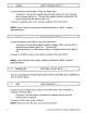
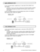
BLACK/WHITE
NEUTRALSAFETYINPUT(-)
Locate the vehicle's neutral safety circuit.
Verification: This wire registers ( - ) voltage when the vehicle's gear
selector is
in
park
or
neutral.
Connect the BLACK/WHITE neutral safety input wire to the neutral safety wire of
the vehicle or an optional toggle switch. The remote start feature will not operate
unless this input is supplied with a ground source.
7
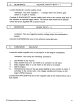
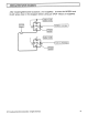
BROWN/RED
BRAKE INPUT ( + )
Locate the vehicle's brake light wire
at
the brake pedal mounted switch.
Verification: This wire registers positive voltage when the brake pedal is
pressed.
Connect
the BROWN/RED wire to the vehicle's brake light wire.
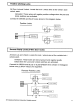
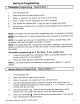
8 PURPLElWHITE
TACH
INPUT
Locate the vehicle's ignition coil
or
fuel injector in the engine compartment.
Verification: Test using the following procedure:
1.
Set voltmeter to AC VOLTS.
2. Attach positive lead of a volt
meter
to a constant 12 volt source.
3.
Attach negative lead of a volt
meter
to the wire to be tested.
4. Start the engine.
5.
Have someone press on the gas pedal slightly as you monitor the meter. If
connected to the correct wire, the voltage reading will increase as the
engine's RPM increases.
Connect
the PURPLE/WHITE wire to the negative side
of
the vehicle ignition coil
or
fuel injector.
2010 Audlovox Electronics Corporation. All rights reserved.
13