
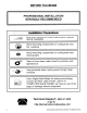
Installation guide
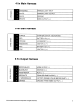
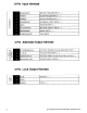
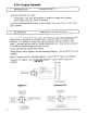

6 Pin Output Harness
1
BROWN/BLACK
HORN
OUTPUT
( - )
Locate the vehicle's horn wire.
Verification: This wire will register
at
positive voltage and register
ground
when
the horn switch is pressed.
Connect
the
BROWN/BLACK
wire
to the vehicle's horn wire. This is a low current
output, 500mA.
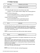
2
BLUE/BLACK
IGNITION
3/
ACTIVE
OUTPUT
( - )
The
Active OutpuVlgnition 3
output
wire provides a ground
output
when the remote
start function is activated and remains until 4 seconds after the remote start is
shutdown.
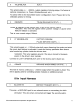
The
Ignition 3
output
wire can be used for several functions listed
below. If this
wire
will be used for multiple application's a 1
amp
diode is required
in-line with the stripe facing the control module.
Factory
transponder
(coded key) bypass.
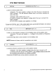
General Motors VATS bypass, see the following diagram.
Use
an SPOT relay (not
supplied).
Ignition 3 output, see the following diagram. Use an SPOT relay (not supplied).
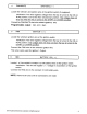
Accessory
2/3
output, see the following diagram. Use an
SPOT
relay (not
supplied).
GM
VATS
BLUE/BLACK
ActlveOutput
Wire
2010 Audiovox Electronics Corporation. All rights reserved.
10
Jump
To
PINK
Ignition Output
Wire From
Control Module
Ignition 3
BLUE/BLACK Active
Output
Wire
Accessory 2/3
Jump
To ORANGE
Accessory Output
Wire From
Contro!
Module
BLUEiSLACK
ActIVe Output
Wire