
Installation guide

1
2
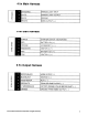
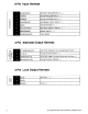
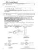
4 Pin Main Harness
WHITE/RED
WHITE
PARKING LIGHT INPUT
PARKING LIGHT OUTPUT
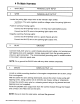
Locate the parking light output wire
at
the vehicle's light switch.
Verification: This
'vvire
registers positive voltage when the parking iights are
turned on.
Positive switching Parking Lights:
Connect
the WHITE/RED wire to a 15
Amp
max fused battery source.
Connect
the WHITE wire to the parking light output wire.
Negative switching Parking Lights:
Connect
the WHITE/RED wire to a good chassis ground.
Connect
the WHITE wire to the parking light output wire.
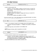
3
BLACK
GROUND
Connect
the
BLACK
wire to a solid chassis ground point using a ring terminal and
self tapping screw (not supplied). Scrape
away
paint from the grounding point to
ensure a good connection. The recommended grounding point is a metal surface
in the driver's side kick panel area.
NOTE: Do not ground the BLACK wire with any other vehicle components.
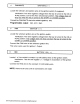
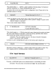
4
BROWN
SIREN
OUTPUT
( + )
Locate a suitable mounting location
in
the engine compartment for the siren,
away
from moving parts.
With the bell
of
the siren aiming downwards, secure the siren in place using self
tapping screws, being careful not do drill into
any
hoses, wiring
or
components.
Connect
the
BLACK
siren wire to a chassis ground using a ring terminal and self
tapping screw (not supplied).
Route the
BROWN
siren output wire from the control module through the firewall
and connect to the RED wire on the siren.
NOTE: Be sure to loom the siren
Wires,
and seal the grommet.
2010 Audiovox Electronics Corporation. All rights reserved.
7