PROFESSIONAL SERIES Owner’s Guide For Models: CA 6551 CA 6551 SST Deluxe Vehicle Security and Remote Start System with 2 Way Confirming LCD Remote Control IMPORTANT NOTE: The operation of the Security and Convenience System as described in this manual is applicable to most vehicles. However, due to the configuration of some vehicles, some functions AND/OR SAFETY PRECAUTIONS may not apply. Please see your installing dealer for more information. 2010 Audiovox Electronics Corporation. All rights reserved.
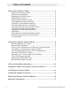
Table of Contents Using Your Remote Control ............................................................... 3 Arming the Security System ............................................................ 3 Passive Arming Bypass ................................................................... 3 Bypassing the Shock Sensor .......................................................... 3 Hidden Alarm Function ...................................................................... 3 Disarming the Security System .......
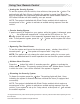
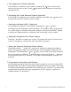
Using Your Remote Control Arming the Security System To arm the system, exit the vehicle, close all doors, then press the button. The parking lights will flash 2 times, indicating the system is armed, has locked the doors (if equipped and connected) and activated the starter disable feature. The LED status indicator will blink steadily, once per second.
Two Stage Door Unlock (Optional) button one time will If this feature is enabled on your system, pressing the unlock only the driver’s door. Press again within three seconds to unlock the remaining doors. Activating the Trunk Release Feature (Optional) If this feature is enabled on your system, pressing and holding the seconds will open the vehicle’s trunk or hatch.
Valet Mode When valet mode is activated the status LED will light solid, and all security functions will be disabled. To enter or exit valet mode simply follow the 4 steps outlined below: 1. Turn the vehicle’s ignition ON. 2. Push and hold the programming/valet button. 3. The LED will turn on solid when valet mode is active 4. Release the programming/valet button.
Car Jack Mode This feature must be turned on in system programming, please consult your installing dealer. Triggering Car Jack mode: While the ignition is ON and press and hold + for 2 seconds, the parking lights will flash 1 time and the system will act as follows; 1. 50 seconds after being triggered the siren will chirp for 15 seconds, during this 15 seconds you will be alerted to push the valet button to turn off Car Jack mode.
Entering the Vehicle while it is Running via Remote Vehicle Start 1. Unlock the vehicle’s doors. 2. Enter the vehicle. DO NOT PRESS THE BRAKE PEDAL! 3. Insert the key into the ignition switch and turn to the ON or RUN position. 4. Press the brake pedal. The remote vehicle starter will disengage and the vehicle will operate normally. Preheating or Precooling the Vehicle’s interior Before exiting the vehicle, set the temperature controls to the desired setting and operation.
Operating the 2 / 3 Hour Start Up Timer Mode The system has the ability to start the vehicle every 2 or 3 hours for a 48 hour period. This feature is especially useful in cold climates where the only means to keep the engine and engine fluids warm is to periodically start the engine. The default setting is 3 hour, Selection between 2 or 3 hour is made in option programming. WARNING! Be certain that the vehicle is outdoors before using this or any remote starting device.
Operating the Daily Start Timer The system has the ability to start your vehicle based on a 24-hour countdown timer. This feature requires a two-part activation sequence. From the remote, & buttons together will activate the 24 hour countdown pressing both the timer (the vehicle will start 24 hours from this time). Next, When you are finished operating the vehicle for the day, perform the following steps to complete the process. 1. Turn the ignition ON/OFF (vehicle must be disarmed). 2.
LED and Siren/Horn Indications LED Display Indications LED Function OFF DISARMED SLOW FLASH ARMED FAST FLASH PASSIVE ARMING ON (SOLID) VALET MODE 2 FLASH... PAUSE ZONE 2 TRIGGER, HOOD/TRUNK 3 FLASH... PAUSE ZONE 3 TRIGGER, DOOR 4 FLASH... PAUSE ZONE 4 TRIGGER, SHOCK 5 FLASH...
Additional 2-Way LCD Remote Control Functions Check Vehicle Status 2 times then press within 3 seconds, the transmitter will Press and release respond with one melody sound and display the current status of the vehicle. Display Illumination Press and hold the seconds. button for 1 second.
Button Lock Press and release then press hold the for 2 seconds to toggle the button lock on or off. When the button lock is active, the remote control will beep/vibrate 2 times when a button is pressed indicating it is locked. Illumination Press and release 2 times then press and hold for 2 seconds to toggle illumination on or off. When on, the display will illuminate when it receives or sends a command.
LCD Remote Control ICON’s LOCK UNLOCK SYSTEM ARMED VALET MODE TRANSMITTING IGNITION ON/TRIGGER TRUNK TRIGGER DOOR TRIGGER HOOD TRIGGER FULL SHOCK TRIGGER SYSTEM TRIGGER TIME COUNT DOWN BATTERY INDICATOR BATTERY SAVE MODE VIBRATE/SILENT MODE MELODY MODE 2 CAR MODE TIME DISPLAY ALARM CLOCK ENGINE RUNNING TIMER START MODES AUX 1 OUTPUT 2010 Audiovox Electronics Corporation. All rights reserved.
Transmitter Button Functions 1 Way Transmitter Lock Lock Car Find / Panic Start X Operation Method Press and Release Unlock X Press and Release 2 Step Unlock X Press and Release 2 times Trunk X Push and Hold (3 Sec) Car Finder X Press and Release Panic X Push and Hold (3 Sec) Remote Start X Press and Release (1 or 2 times depending on selectable option) Remote Start Shutdown X Push and Hold (3 Sec) Run Time Extention X Press and Release 4 times.
2 Way Transmitter Lock Lock Unlock Car Find / Panic Start Function Operation Method X Press and Release Unlock X Press and Release 2 Step Unlock X Press and Release 2 times Trunk X Push and Hold (3 Sec) Car Finder X Press and Release Panic X Push and Hold (3 Sec) Remote Start X Press and Release (1 or 2 times depending on selectable option) Remote Start Shutdown X Push and Hold (3 Sec) Run Time Extention X Press and Release 4 times.
Replacing Remote Control Batteries 1 Way 4 Button Remote Control - CA6551 / CA6551SST The batteries inside each remote control should last approximately 1 year under normal use. When the batteries become weak you will notice the remote control range (the distance from the vehicle the remote control will work) deteriorate and the small LED on the remote control will dim. To replace the remote control batteries: 1. Remove 3 screws and disassemble the halves of the remote control. 2.
Code Systems, Inc. Limited Lifetime Warranty Code Systems Inc.
Audiovox Electronics Corporation. Customer Service 1-800-421-3209 WWW.CODE-ALARM.COM FCC COMPLIANCE This device complies with Part 15 of the FCC rules and with RSS-210 of Industry Canada. Operation is subject to the following two conditions: 1. This device may not cause harmful interference, and 2. This device must accept any interference received, including any interference that may cause undesired operation.
C[J[Jc:~VJ~m ~rlOFESSIONAL SErllES Security and Remote Start Installation Guide for models: CA 6151 CA 6551 CA 6551 SST 2010 Audiovox Electronics Corporation. All rights reserved.
Table of Contents Before You Begin 4 Wire Connection Guide 5 4 Pin Main Harness 6 Pin Start Harness 7 8 6 Pin Output Harness 10 8 Pin Input Harness 11 4 Pin Alternate Output Harness 14 3 Pin Door Lock Output Harness 16 Additional Ports 20 Antenna / LED / Programming Port 20 DBI Port 20 Tracking Port 20 Set Up & Programming 2 , 21 Transmitter Programming 21 Manual Feature Programming 21 Programming Feature Banks 22 Tach Programming 23 Smart Tachless Mode 24 Adjusting the
Feature Descriptions 25 Transmitter Button Functions 30 Security Trigger Zones 31 Remote Start Shutdown Diagnostics 31 System Layout 32 2010 Audiovox Electronics Corporation. All rights reserved.
BEFORE YOU BEGIN PROFESSIONAL INSTALLATION STRONGLY RECOMMENDED Roll down window to avoid locking keys in vehicle during installation Avoid mounting components or routing wires near hot surfaces Avoid mounting components or routing wires near movin g pa rts Tape or loom wires under hood for protection and appearance . Use grommets when routing wires through metal surfaces Use a Digital Multi Meter for testing and verifying circuits.
4 Pin Main Harness z WHITE/RED PARKING LIGHT INPUT ~ WHITE PARKING LIGHT OUTPUT a.. BLACK GROUND BROWN SIREN OUTPUT ( + ) « z ~ 6 Pin Start Harness l- c::: ~ z (/) a..
8 Pin Input Harness BLUEIWHITE INSTANT TRIGGER INPUT ( - ) GREEN DOOR TRIGGER INPUT ( - ) PURPLE DOOR TRIGGER INPUT ( + ) z z WHITE/BLUE EXTRENALSTARTINPUT(-) GRAY HOOD PIN INPUT ( - ) co BLACKIWHITE NEUTRALSAFETYINPUT(-) BROWN/RED BRAKE INPUT ( + ) PURPLEIWHITE TACH INPUT t- ~ a.. a..
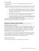
4 Pin Main Harness 1 WHITE/RED PARKING LIGHT INPUT 2 WHITE PARKING LIGHT OUTPUT Locate the parking light output wire at the vehicle's light switch. Verification: This 'vvire registers positive voltage when the parking iights are turned on. Positive switching Parking Lights: Connect the WHITE/RED wire to a 15 Amp max fused battery source. Connect the WHITE wire to the parking light output wire. Negative switching Parking Lights: Connect the WHITE/RED wire to a good chassis ground.
6 Pin Start Harness 1 PURPLE STARTER OUTPUT ( + ) Locate the vehicle starter wire. Verification: This wire registers voltage only when the key is turned to the START position. Cut the vehicle's starter wire in half when installing the starter kill relay. Verification after starter wire is cut: KEY SIDE of starter wire registers voltage when the key is turned to the START position. MOTOR SIDE of starter wire registers no voltage.
4 IGNITION 2 ( + ) PINKtWHITE Locate the vehicle's 2nd ignition wire at the ignition switch (if equipped). Verification: This wire registers voltage when the key is turned to the ON (or RUN) position, but not the ACC (Accessory) position. The voltage does not drop out when the key is turned to the START (or CRANK) position. Connect the PINKIWHITE wire to the vehicle's ignition 2 wire. Programmable output: 5 PINK IGN, ACC, Start.
6 Pin Output Harness 1 BROWN/BLACK HORN OUTPUT ( - ) Locate the vehicle's horn wire. Verification: This wire will register at positive voltage and register ground when the horn switch is pressed. Connect the BROWN/BLACK wire to the vehicle's horn wire. This is a low current output, 500mA.
3 VIOLET/BLACK AUX 1 This wire provides a (-) SOOmA output capable of driving relays. For Control of optional accessories (i.e. Power Window/Sunroof, etc.). To activate refer to the transmitter button configuration chart. Please refer to the selectable options for timing. 4 TRUNK RELEASE OUTPUT ( - ) REDIWHITE Locate the vehicle's trunk release wire at the trunk release switch. Verification: This wire will register either positive voltage or ground when the trunk release is activated.
2 GREEN DOOR TRIGGER INPUT ( - ) Locate the vehicle's dome light or door pin switch wire. Verification: This wire will register ground (NEG) when the door is opened and the interior light is on. This wire will register positive voltage when the door is closed and the interior light is off. Connect the GREEN wire to the vehicle's negative door input wire(s). NOTE: Certain vehicles may require multiple connections. Refer to vehicle application gUide.
6 NEUTRALSAFETYINPUT(-) BLACK/WHITE Locate the vehicle's neutral safety circuit. Verification: This wire registers ( - ) voltage when the vehicle's gear selector is in park or neutral. Connect the BLACK/WHITE neutral safety input wire to the neutral safety wire of the vehicle or an optional toggle switch. The remote start feature will not operate unless this input is supplied with a ground source. 7 BRAKE INPUT ( + ) BROWN/RED Locate the vehicle's brake light wire at the brake pedal mounted switch.
4 Pin Alternate Output Harness 1 LT GREEN/BLACK FACTORY DISARM / PULSE BEFORE START ( - ) This wire will supply a ( - ) 500mA pulse both upon disarming the system and when the remote start feature is activated. Locate the factory perimeter alarm disarm wire from the key cylinder inside the drivers door. Verification: This wire registers ground if the key is turned to the unlock position in the driver's door cylinder. Connect the LIGHT GREEN/BLACK wire to the factory alarm disarm wire.
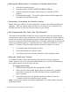
4 PULSE DURING CRANK ( - ) BLACK/YELLOW Locate the vehicle's second starter (crank) wire at the ignition switch. (if equipped) Verification: This wire registers voltage only in the start (crank) position of the ignition switch. Connect the BLACK/YELLOW wire as shown in the diagram below. Use an SPOT relay (not supplied). Fused +12 Volt Battery SOUr( e Jump To PURPLE S tarter Output 1---+11 Wire From The Control Module 2010 Audiovox Electronics Corporation. All rights reserved.
3 Pin Lock Output Harness 1 BLUE UNLOCK ( - ) 3 GREEN LOCK ( - ) The door lock / unlock outputs are designed to control several different types of systems which may require additional parts. Please review the wire and location chart to see which type of door lock system is in your vehicle. The most common types are shown in the following diagrams. Negative SWitching Locks All Door Lock and Unlock: Locate the lock / unlock wire at the vehicle's lock / unlock switch.
Positive Switching Locks All Door Lock and Unlock: Locate the lock / unlock wire at the vehicle's lock / unlock switch. Verification: These wires will register positive voltage when the Lock and Unlock switches are activated. Connect the GREEN and BLUE wires shown in the diagram below.
Negative MUltiplexed Locks All Door Lock and Unlock: Locate the lock / unlock wire at the vehicle's lock / unlock switch. Verification: This wire will show variable ground when the switch is activated. Please consult the wire and location chart for specific resistor values for your vehicle. Connect the GREEN and BLUE or BLUE/GREEN wires shown in the diagram below using (2) SPOT relays (not supplied). Multiplex Locks: .
Adding Aftermarket Actuators After installing aftermarket actuators, (not supplied). Connect the GREEN and BLUE wires shown in the diagram below using (2) SPDT relays (not supplied). , . - - - - i__- - - t Fused +12 Volt Battery Source GREEN (.j Lock Output 86 ,,------1.....----1 Fused +12 Volt 87 86 2010 Audlovox Electronics Corporation. All rights reserved.
Additional Ports Antenna I LED I Programming Port Mount the supplied antenna/receiver to a clear spot on the vehicle's windshield that will not block the driver's vision. A good location is usually high on the windshield near the rear view mirror. Be careful not to mount the antenna/receiver on any metallic window fiim, as this will effect system range. Route the antenna! receiver cable to the control module and plug into the antenna port.
Set Up & Programming Transmitter Programming - Feature Bank 1 1. Turn the ignition ON. 2. Press and hold the valet/override button. 3. Within 10 seconds the system will chirp (3) three times. 4. Press 1 button of each transmitter you wish to program. 5. The system will respond with 1 chirp for each accepted transmitter. 6. Pressing the override button at anytime during programming will advance to the next bank. NOTE: The system will exit transmitter programming after 15 seconds of inactivity.
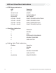
a Defaulting All Features: Pressing the button anytime while In any of the feature banks will default all features and return you to feature bank 2 - 4 chirps. NOTE: The system will remain in feature programming mode as long as the ignition is on, there is no time limit. To exit programming turn the IGNITION OFF. Feature Bank 1 - 3 Chirps Transmitter Programming Refer to transmitter programming. Feature Bank 2 • 4 Chirps Security Control 1 LED Flash '. C . ' . 1 SIlent ChoiCe 2 .
Feature Bank 4 - 6 Chirps Remote Start Control 1 RF.Staft Chirp 2 Run Time 1 LED Flash 2 LED flash Ott OFF 15 Minutes 5 Minutes 3 LED Flash 4 LED Flash 5 LED Flash 6 LED Flash 10 Minutes 20 Minutes 45 Minutes 60 Minutes 3 RunnIog Ught8 ... Steady Tach Mode Tach Tachless Hybrid (Crank (Crank Average Average I NO I Voltage) Voltage) 5 VoItag8 .Level "1Qh low 6 1.0 Seconds 0.8 Seconds 4 Crank Time Ft-.l1iog .' 1.5 Seconds DBIPort 2.
NOTE: If the unit fails to learn tach rate due to an improper tach connection or a poor tach source, the parking lights will not flash. To correct this situation, locate and connect the PURPLE/WHITE wire to the proper tach signal, and then repeat the tach learn routine.
Dome Light Delay I Theater Dimming The system can be programed to delay arming after the lock button is pressed (60 second max) for vehicles with a dome light delay or theater dimming feature. Once programed the system will 'learn' the timing of the dome light delay and add 2 seconds before arming. 1. Close all doors with ignition off. 2. Using the transmitter press LOCK, UNLOCK, LOCK ,UNLOCK, LOCK, UNLOCK, LOCK. The LED will light solid to indicate the system has entered DOME DELAY LEARN MODE. 3.
4 - Siren I Horn: This feature selects which output(s) will sound the system's arm/disarm chirps. This feature does not effect the triggered state of the security system and during a triggered cycle, both the siren and horn outputs will activate respectively. 5 - Security: Controls security functionality - ON / OFF. ON - Full security functionality. OFF - The security system does not trigger.
3 - Ignition Controlled Locks: Control of door locks when the ignition is cycled ON or OFF. OFF - Door locks not activated by ignition. Lock and Unlock - Doors lock when ignition is turned on and unlock when ignition is turned off. Lock Only - Doors lock when ignition is turned on. Unlock Only - Doors unlock when ignition is turned off. 4 - Horn Output Timing: Control the minimum horn pulse time in milli seconds, some vehicle will require a longer pulse to activate the factory horn.
4 - Tach Mode: Determines how the system monitors the engine running during remote start. Tach - Hard wired directly to the tach wire of the vehicle to monitor AC voltage. Tachless (Crank Average/Voltage) - Determines crank time by averaging the last 8 times the vehicle was started with the key and then monitors the change in voltage after remote start. Hybrid (Crank Average / No Voltage) - Determines crank time by averaging the last 8 times the vehicle was started with the key.
9 - Single I Double Pulse Start: Switches the remote start activation between a single or double press from the transmitter. 10 - IGN 2 Output: Programmable high current output. Ignition 2 - Ignition output during remote start. Accessory - Accessory output during remote start. Start / Crank - Crank output during remote start. 11 - 2 or 3 Hour Start: When activated, the remote start will activate and run for the programmed time and shut down every 2 or 3 hours.
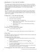
Transmitter Button Functions lW~ Transmitter Lock Car Find! Panic Unlock Start Op_on_od X Lock Press IIld Rele.,e Press and Release Unlock 2 StIp UnlOCk X PreSs and Reiease Trunk X Push and HOldl3 Sec) X Car"'" 211m"S press and Release Panic Push ana Hold (3 Sec) R... otestart Prilss and Rl!le8!Se(t X .' or 2Umes dipendtlgoo SeleciZl,dpUOIl) Remote Stort Shutdown PuSh ana Hold 13 Sec) Run Til... , Press and Releate 411m.~. X 1AUX 1 Push ana Hold (3 SeC) J( ShOCkBypI" .
Security Trigger Zones If the security system has been triggered the LED will flash one of the patterns below indicating the zone. LED FLASHES TRIGGER ZONE 2 Flashes Hood / Trunk Input 3 Flashes Door Input 4 Flashes Shock Sensor 5 Flashes Ignition Input Remote Start Shutdown Diagnostics If the remote start shuts down or fails to start, the parking lights will flash one of the patterns below indicating the shutdown input.
2010 Audiovox Electronics Corporation. All rights reserved.
Audiovox Electronics Corporation. Customer Service 1-800-421-3209 WWW.CODE-ALARM.COM FCC COMPLIANCE This device complies with Part 15 of the FCC rules and with RSS-210 of Industry Canada. Operation is sUbject to the following two conditions: 1. This device may not cause harmful interference, and 2. This device must accept any interference received, including any interference that may cause undesired operation.
R41 0-192-01 0
WARNING THIS VEHICLE IS EQUIPPED WITH A REMOTE CONTROLLED CAR STARTER BEFORE SERVICING THIS VEHICLE, REMOVE THE MAIN POWER FUSE (RED WIRE) TO THE CAR STARTER OR DISCONNECT THE VEHICLE BATTERY.
Thank you for purchasing a Code-Alarm product. We pride ourselves on the quality and reliability of all our electronic products, but if you ever need service or have a question, our customer service staff stands ready to help. Contact us at www.Code-Alarm.com PRODUCT PROTECTION: In case of an insurance loss such as fire, flood or theft, your registration will serve as proof of purchase.
Register online at: .CODE-AlARM.
MAXIMUM INSURANCE DISCOUNT AUTHORIZATION Dear Insurance Agent, The installation of my Code-Alarm automatic (passive) arming security sys1em in the vehicle indicated below qualifies me for the maximum discount mandated by law in some states and by insurance company option in others. This vehicle security system automatically arms itself after the doors are closed and includes at least one engine disabling relay to prevent the engine from being started.
$2,500.00 L I M I E T o w A R R N A y T CODE SYSTEMS. Inc makes the following warranty to YOU as the original purchaser of this system. Should YOUR private passenger vehicle in which the CODE-ALARM ANTI-THEFT SYSTEM is originally installed by an authorized dealer and while the system is operational and activated be stolen and not recovered or if stolen and recovered be deemed a total loss for theft insurance purposes. then subject to the following conditions.
The CODE-ALARM Program Administrator reserves the right to ask for any other similar documentation or other materials that may be reasonably required to verify YOUR claim. All documentation received on a claim becomes the Code-Alarm Program Administrator's property and will not be returned. All claim information must be mailed to the Code-Alarm Program Administrator within thirty (30) business days after receipt of the final settlement check from YOUR insurance carrier.