
Technical data

E2 Setup of Devices ECT MODBUS Networking to E2s • 37
An E2 has three COM ports that can be assigned
for MODBUS communication (COM2). COM ports
can only be used for one function; in other words, if
COM2 is set up as the I/O network, you cannot con-
nect MODBUS devices to COM2. Ensure your E2 is
configured in E2 General Services (
,
Serial tab) to enable COM4 or COM6.
Connect the MODBUS network cable to the three-
terminal connector on the COM port you wish to as-
sign as MODBUS. Reverse polarity of +/- on RS485
cable from E2 to the device.
22.3.E2 Setup of Devices
22.3.1.Set Up Network Ports
Before setting up a device, the port on the E2 that
has the MODBUS cable connected must be set up as
a MODBUS port.
1. Log in to the E2 with Level 4 access.
2. Press
followed by - General
Controller Info.
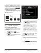
3. Press
+ to open the Serial tab of the General
Controller Info setup screens:
4. This screen will have a “Connection” field for all
COM ports on the E2. Highlight the COM port con-
nection field that will be used for the device, and
press - LOOK UP. From the list of network
types, select MODBUS.
5. Four fields will become visible underneath the
COM port connection field, which pertain to the
way the device communicates:
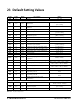
• Baud - Default setting is 19.2k. The baud rate set-
ting should be set to match the baud rate of the
XR670K - XR679K device (9600). (All devices
connected to the same COM port should be set to the
same baud rate.)
• Data Size - Leave this field at the default value (8).
• Parity - Leave this field at the default value (None).
• Stop Bits - Leave this field at the default value (1).
6. Press
to save changes and exit.
22.3.2.Add and Connect the Device
To enable communications between E2 and the
XR670K - XR679K units, the devices must be added
and addressed in E2.
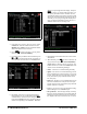
1. Log in to the E2 with Level 4 access.
2. Press
- Connected I/O Boards
and Controllers.
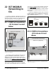
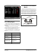
Figure 22-4 - MODBUS Networking
E2
XR670K/
XR679K
#1
TERMINATED,
BIASED
(ALL 3 JUMPERS
IN UP POSITION)
XR670K/
XR679K
#2
XR670K/
XR679K
#3
Figure 22-5 - Serial Communications Manager Screen