
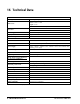
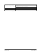
Technical data
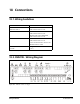
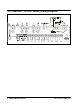
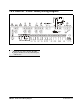

XM679K - 24VAC Valves/Wiring Diagram Wiring Layout for Sharing a Pressure Transducer on a LAN • 33
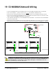
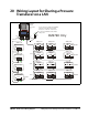
20 Wiring Layout for Sharing a Pressure
Transducer on a LAN
Figure 20-1 - Wiring Guidelines for Sharing a Pressure Transducer Across Multiple Units on the Same Circuit - XM679K Only
XM679K
Address01
LAN
RS485
Black
White
MultiFlex XXX+
Address01
RS485
Black
White
Ground
RS485
Black
White
Ground
Black
White
Black
White
XM679K
Address02
XM679K
Address08
Circuit 1
XM679K
Address09
XM679K
Address10
XM679K
Address16
Circuit 2
XM679K
Address17
XM679K
Address18
XM679K
Address24
Circuit 3
XM679K
AddressXX
XM679K
AddressXX
XM679K
AddressXX
Circuit X
MultiFlex XXX+
Address02
RS485
MultiFlex XXX+
Address03
RS485
MultiFlex XXX+
AddressXX
RS485
LAN
RS485
LAN
RS485
LAN
RS485
LAN
RS485
LAN
RS485
LAN
RS485
LAN
RS485
LAN
RS485
Black
White
Black
White
Black
White
Black
White
Black
White
Black
White
Black
White
Black
White
Black
White
Black
White
Black
White
Black
White
Black
White
Black
White
Black
White
Black
White
Black
White
Black
White
Black
White
Black
White
Black
White
Black
White
Black
White
Ground
Black
White
Ground
Black
White
Ground
Termination
I/O Board
+
+
Ground
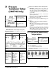
Do not connect the shield of the MODBUS
network to the E2 PIB center terminal.
Instead, use a 100 ohm ½ watt resistor
to connect the MODBUS cable shield to
earth ground
100 ohm
1/2 watt
+
+
RS485
RS485
RS485
+
+
+
+
+
+
+
+
+
+
+
+
+
+
+
+
+
+
+
+
+
+
LAN
RS485
LAN
RS485
LAN
RS485
Shield
Shield
Shield
Shield
+
+
+
+
MODBUS
Network
Term
Set E2 to 9600
baud
Ter m
Termination Block
A maximum of 8 devices are allowed on LAN
36
37
38
39
36
37
38
39
36
37
38
39
36
37
38
39
36
37
38
39
36
37
38
39
36
37
38
39
36
37
38
39
36
37
38
39
36
37
38
39
36
37
38
39
36
37
38
39
COM4
COM2
XM679K Only