
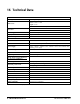
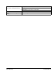
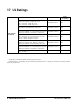
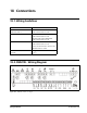
Technical data

32 • XM670K-XM679K I&O Manual 026-1218 Rev 0 19-DEC-2012
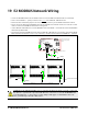
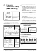
19 E2 MODBUS Network Wiring
• Connect the MODBUS Network to the RS485 Connector on the E2 PIB board (Belden 8641 recommended).
• Note to wire the RS485 +/- polarity at the E2 in the reverse
of the XR670K - XR679K devices.
• Position the three termination jumpers to the UP (terminated) position to provide RS485 termination at the E2.
• Do not connect the shield of the MODBUS network to the E2 PIB center terminal. Instead, use a 100 ohm 1/2 watt
resistor to connect the MODBUS cable shield to earth ground.
• At each XR670K - XR679K device, wire the MODBUS cable to the RS485 +/- terminals and connect the MODBUS
shield to the pin 18 terminal.
• Terminate the end of the MODBUS network at the last XR670K - XR679K device on the daisy chain with the MOD-
BUS termination block (P/N 535-2711), or by connecting a 150 ohm resistor between the MODBUS +/- terminals.
Figure 19-1 - XR670K - XR679K to E2 MODBUS Network Wiring
LON
EARTH GROUND
AC1
Shield
24VAC
Keyboard
RS-232
AC2
ON
OFF
LON
RS485-1B
+ 0v -
E2 STANDARD (3.XX and Below Version)
POWER INTERFACE BOARD (PIB)
237-4810,Version1.00
E2 PowerInterface Board(P.I.B.)
R
Echelon Terminate Up
+ 0V -
RS485-2B
TX1
RX2
RX1
JP4
JP5
JP6
JP1
JP2
JP3
REVERSE POLARITY OF +/-
ON RS485 CABLE FROM E2
BELDEN 8641
(TYPICAL)
earth ground connection
100 ohm
Watt
1/2
18 17 16 15 14 13 12 10 9 7811 321
19 20 22 23
24
25
26
39
38
37
36
35
34
33
32
31
30
29
28
27
21
+
RS485
-
+
modbus
B
l
a
c
k
W
h
i
t
e
XM67XK Series
S
h
i
e
l
d
MODBUS TERMINATION
BLOCK 537-2711
150 ohm
18 17 16 15 14 13 12 10 9 7811 321
19 20 22 23 24 25 26 3938
37
36
35343332313029282721
+
18
17 16 15 14 13 12 10 9 7811 321
19 20 22 23 24 25 26 3938
3736
35343332313029282721
+
RS485
-
+
modbus
Black
White
RS485
-
+
modbus
Black
White
BELDEN 8641
(TYPICAL)
Shield
Shield
XM67XK Series
XM67XK Series
Position the three
jumpers to provide
RS485 termination
at the E2
TERMINATE NETWORK
+ 0v -
637-4890
White +
Black -
RS485-2A
+ 0V -
9600 Baud Only
*Note that for E2 Enhanced PIB
boards, the RS-485 connection
can be wired on COM 2, COM 4,
or COM 6.
MODBUS 485
MODBUS 485
CAUTION! For the XR, XM, and XEV series of controllers, the shield wire must not come into contact with
any other wire or ground source. If contact with other wires or devices does occur, the 485 MODBUS net-
work will malfunction or connected devices will be damaged. This applies to all installations where the
shield is tied to ground through a 100 ohm ½ Watt resistor.