
Technical data

11/98
©1995 Square D—All Rights Reserved
8
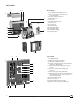
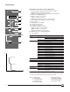
STR 28D Control Unit for General Application
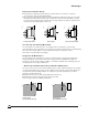
1. Mechanical pop-out type fault indicator and reset button:
n Indicates that a fault trip has occurred
n Prevents closing of the circuit breaker after fault until reset
2. Ammeter (LCD digital display)
3. Ammeter selector used to read:
n Phase currents (1, 2, 3, N)
n Or the phase with the highest load current (max.)
4. Load indication (bar graph in % of current setting)
5. Sensor rating
6. Rating plug (on STR 28DP)
7. Long-time current setting
8. Instantaneous pickup
9. Local and remote pre-trip alarm:
n LED on at 90% of current setting
n LED flashing on overload (1)
n Remote indication by static contact
10. Available spaces for setting identification
11. Test receptacle
06313016 06313015
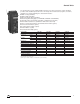
Overcurrent Protection—RMS Sensing
Long-time Current Setting STR 28DP: 0.8 to 1 x Rating Plug (Pickup at 1.1 x Setting)
STR 28D: 0.4 to 1 x Current Sensor (Pickup at 1.1 x Setting)
Max. Delay Fixed: 7.5 sec. at 6 x Current Setting
Rating Plug Current Sensor Plug Rating
250 A 250–200–150–125 A
400 A 400–300–250–200 A
600 A 600–500–400–300 A
800 A 800–600–500–400 A
1200 A 1200–1000–800–600 A
1600 A 1600–1200–1000–800 A
2000 A 2000–1600–1200–1000 A
2500 A 2500–2000–1600–1200 A
3000 A 3000–2500–2000–1600 A
3200 A 3200–3000–2500–2000–1600 A
4000 A 4000–3200–3000–2500–2000 A
5000 A 5000–4000–3200–3000–2500 A
6300 A 6300–6000–5000–4000–3200–3000 A
Instantaneous Pickup 1.5 to 10 x Current Setting
Built-in Ammeter (Optional)
Option I Values Displayed Phase 1, 2, 3, Max., Neutral Current
Accuracy ±1.5 % (2)
Bar Graph Indication Phase 1, 2, 3—10% Steps
Control Power Not Required (3)
Fault or Alarm Indicators
Not Discriminated Local Pop-out Type Indicator and LED Pre-trip Alarm
Remote Overcurrent Trip and Pre-trip Alarm Switches
(see pp. 14–15)
(1)According to time-current curves: between 105% and 120% of current setting.
(2)Total accuracy including current sensors: ±4.5%.
(3)Control power not required for loads greater than 20% of current sensor. Required for load less than 20%
of current sensors if maximum demand memory requested (see diagram on p. 43).
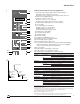
I
t
Long-time Setting
Instantaneous
Note: Io: Rating plug
In: Sensor rating
Ir: Long-time pickup
tr: Long-time delay
Im: Short-time pickup
push to reset
I
I1 I2 I3
90%
50%
20%
STR 28 D
90
105
%Ir
.88
.9
.92
.95
.98
1
.8
.85
xIo
Im
3
45
6
8
101.5
2
xIr
Ir
Im
t
i
test
+ –
Ir :
Im :
1
2
4
3
6
Ir
7
8
9
10
11
5
Control Units
tm: Short-time delay
I: Instantaneous pickup
Ih: Ground-fault pickup
th: Ground-fault delay