
Technical data

11/98
©1995 Square D—All Rights Reserved
44
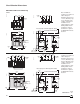
Wiring Diagrams
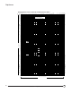
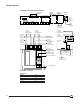
SC150 Indication and Control Interface
06313085
Internal Bus
Marking Color
24 V Red
0 V Black
Internal Bus – White
Internal Bus + Blue
630
24V
0
NC
–+
e+ T–T+e– ON OFFSDE
NO NC ON CD SDV
SD
CE
IN
C1 C2 C3
C4
reset
400
COM
124
24-250V CC
100-440V CA
LN
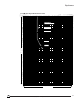
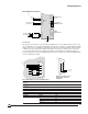
SC150 Indication and Control Interface
DIGIPACT
Internal Bus
To Power
Supply "L"
Control Outputs Inputs
Inputs
External
Contact
To "IN"
SC150
Input
Terminals
To "C4"
SC150
Input
Terminals
Motor
Operator
Power Supply
PT100
Temperature
Probe
To SC150
Terminals
"T+" and "T–"
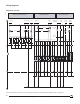
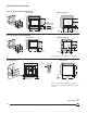
XF MX
M
A4
C2
B4
A1
C1
B1
124
OF
124
SDE
124
CD
124
CE
1
24
e+ e –
12
SDE
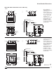
MASTERPACT Circuit Breaker
Control Unit
STR28 / 38 / 58
To Power Supply "L"
to "NO"
SC150 Control
Output Terminals
To "ON"
SC150 Control
Output Terminals
To Power Supply "N"
To "C3"
on SC150
Input Terminals
To "CE"
on SC150
Input
Terminals
To "CD"
on SC150
Input
Terminals
To "OFF"
on SC150
Input Terminals
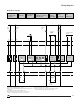
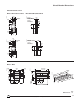
To "C4"
on SC150
Input Terminals
To "ON"
on SC150
Input Terminals
To "SDE"
on SC150
Input Terminals
To "C4"
on SC150
Input Terminals
To "SDE"
on SC150
Input Terminals
To Auxiliary
Source
To "e +" and "e –"
Control Unit
STR58U
Control Unit
on SC150
"COM" Terminals
Remote
Control