
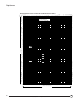
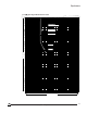
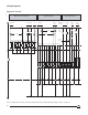
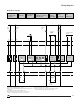
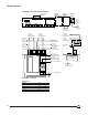
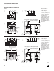
Technical data

43
©1995 Square D—All Rights Reserved
11/98
Diagram No. 689 889
(1)84 terminal not available with Z or C option.
(2)Zone-selective interlocking with downstream circuit breaker: remove
the jumper.
(3)Communication output through DIGIPACT module.
(4)Use 24 Vdc supply for loads less than 20% of current sensor
rating, or one-phase load less than 40% of sensor rating.
06313084
(5)Use 24 Vdc supply for lower setting.
(6)Use 24 Vdc supply for F option if not supplied with PIL (battery)
option; use 24 Vdc supply (mandatory) for FV option.
Wiring Diagrams
Communication
Network
Fault
Alarm
LR2
LR1
1
82 84
81
SDE
LT
Alarm
F1
I Option
F2
24 Vdc
T or W Option
V
LT ST Gnd
F or FV Option
Z21
Z Option
Z22
Downstream
Circuit
Breaker
Out
In
Z11 Z12
Upstream
Circuit
Breaker
Overload
Alarm
T2 T1
Ic1
R1 R2
C
R Option
Ic2
Selected
Fault
C Option
e + e –
S2 S1
Ground-fault
Protection
Remote Fault
and Overload
Indication
Ammeter
Local Fault Indications
and Remote Selected
Fault Indication
Zone-
selective
Interlocking
Load
Monitoring
Data
Transmission
+
_
(2)
(1)
(3)
(4) (5)
(6)