
Technical data

11/98
©1995 Square D—All Rights Reserved
22
Control Units
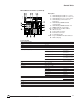
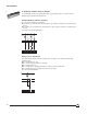
Sizing of the DIGIPACT Internal Bus
Sizing of the DIGIPACT internal bus depends on two factors:
n The number of devices on the bus
n The length of the bus
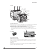
Number of Devices
As on any communications network, the number of devices that may be connected on the
DIGIPACT internal bus is limited. The maximum number of devices is calculated in terms of
"communication points." Each type of device represents a number of points indicated in the table
below. The total number of points for the various devices connected to a single bus must not exceed
100. If the required devices represent more than 100 points, simply add a second DIGIPACT
internal bus with a second DC150 data concentrator. The same sizing rules apply to the second bus
as well.
Communicating Device Number of Points
DC150 Data Concentrator 4
Communicating Auxiliary Switches OF, SD, SDE for COMPACT
®
NS Circuit Breakers 2
Communicating Motor Operator and Auxiliary Switches for COMPACT NS Circuit Breakers 2
Communicating Auxiliary Switches CE and CD for COMPACT NS Circuit Breakers 0
SC150 Indication and Control Interface 4
CLS150 Indication and Local Control Module Associated with:
n Communicating Auxiliary Switches 0
n Communicating Motor Operator and Auxiliary Switches 0
n SC150 Indication and Control Interface 0
PM150 Power Meter 4
ATB MULTI 9 Interface 2
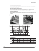
Length of Bus
The table below indicates the cross-sectional area of the cable that must be used depending on the
total length of the bus.
Cross-sectional Area Maximum Length of Bus
0.03 in.
2
(0.75 mm
2
) 660 ft. (200 m)
0.06 in.
2
(1.5 mm
2
) 1310 ft. (400 m)
0.1 in.
2
(2.5 mm
2
) 2300 ft. (700 m)
The total resistance of the two wires for the bus must be less than 12 ohms. If the bus is too long,
simply:
n Increase the cross-sectional area of the cable.
n Create two shorter buses for the installation (in this case, a second DC150 data concentrator
is required).