
Technical data

11/98
©1995 Square D—All Rights Reserved
14
Control Units
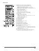
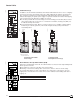
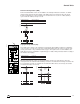
Fault Indicator (F)
In addition to the mechanical fault indicator, this indicator differentiates the three causes of tripping:
overload, short circuit or ground fault, if any. Three light-emitting diodes indicate separately long-
time, short-time/ instantaneous and ground-fault trip. A flat push button allows resetting of the
indicator after tripping. A separate power supply is required to maintain the indication after tripping
of the circuit breaker. Two different possibilities are offered:
n Connecting a reliable 24 Vdc control voltage on F1-F2. Auxiliary power module (AD) is used for
other voltages. When the control source is considered as unreliable, a battery pack (BAT) is to
be added to an AD power module.
n From a built-in battery module. When no external control source is available, a built-in battery
module may be ordered (option PIL). This module integrates battery testing and indicator
reactivating buttons.
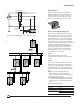
Configuration with Reliable
Control Voltage
Configuration with
Interruptible Control Voltage
06313025
24 Vdc
1W
+
F1 F2
06313026
06313027
+
F1 F2
AD
(1)
F1 F2
+
AD
(1)
BAT
(1)AC: 120 V, 60 Hz
DC: 24–48–125 Vdc
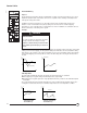
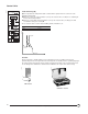
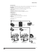
Alarm Indicator Pre-trip Alarm Switch (ALR)
Delivered as standard with control unit. The alarm indicator is a fixed, front face light-emitting diode
which operates as follows:
n Fixed when the current exceeds 90% of the current setting.
n Flashing on overload: according to time-current curves, 105% to 120% of current setting.
The pre-trip alarm switch is a static contact which closes when in the overload zone, up to the
tripping of the circuit breaker. This contact can be used for ultimate load shedding, alarm before
tripping, etc.
Output Characteristics 0.1 A/240 Vac (Optical Triac)
Power Supply Not Required
06313024
Ih
xIn
xIn
Ic1
push to reset
I1 I2 I3
90%
50%
20%
STR 58 U
Ir tr
xIo at 1.5Ir
Im tm
xIo
test
T
R
th
I
Ic2
xIr
xIr
t
i
F
test
06313028
xIn
i
R
push to reset
I1 I2 I3
90%
50%
20%
STR 58 U
t
test
F
test
I
xIr xIr
T
Ih th
xIn
Ic1 Ic2
Ir tr
xIo at 1.5Ir
Im tm
xIo
ALR