
Technical data

11
©1995 Square D—All Rights Reserved
11/98
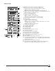
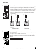
Control Units
Overcurrent Protection—RMS Sensing
Long-time Current Setting STR 58UP: 0.8 to 1 x Rating Plug (Pickup at 1.1 x Setting)
STR 58: 0.4 to 1 x Current Sensor (Pickup at 1.1 x Setting)
Delay Bands 0.94–1.88–3.75–7.50–15–30s at 6 x Current Setting
Thermal Memory as Standard with Min./Max. Selector
Rating Plug Current Sensor Plug Rating
250 A 250–200–150–125 A
400 A 400–300–250–200 A
600 A 600–500–400–300 A
800 A 800–600–500–400 A
1200 A 1200–1000–800–600 A
1600 A 1600–1200–1000–800 A
2000 A 2000–1600–1200–1000 A
2500 A 2500–2000–1600–1200 A
3000 A 3000–2500–2000–1600 A
3200 A 3200–3000–2500–2000–1600 A
4000 A 4000–3200–3000–2500–2000 A
5000 A 5000–4000–3200–3000–2500 A
6300 A 6300–6000–5000–4000–3200–3000 A
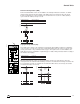
Short-time Pickup 1.5 to 10 x Current Setting
Delay bands 0–0.1–0.2–0.3–0.4 with I
2
t OFF
0.1–0.2–0.3 with I
2
t ON
Zone-selective Interlocking with Option Z (see p. 13)
Instantaneous Pickup Adjustable from 2 to Max. Value (1); Defeatable on N1 and
H1 Types
Ground-fault Protection (Option T or W) (2)
Pickup Delay Band 0.1 x Current Sensor to 1200 A (3)
0.1–0.2–0.3–0.4 with I
2
t Ramp ON/OFF Switch
Zone-selective Interlocking with Option Z (see p. 13)
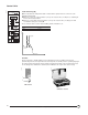
Fault Indicators (Option F)
Not Discriminated Local Mechanical Pop-out Type Indicator and LED Pre-trip Alarm
Remote Overcurrent Trip and Pre-trip Alarm Switches (see pp. 14–15)
Discriminated Local With Option F (see p. 14)
Remote With Option FV (see p. 15)
Built-in Ammeter (Option I)
Values Display Phase 1, 2, 3, Max., Neutral and Ground Current
Accuracy ±1.5% (4)
Bar Graph Indication Phase 1, 2, 3—10% Steps
Control Power Not Required (5)
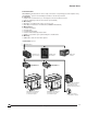
Load Monitoring (Option R)
Inverse Time Alarm Pickups Ic1 = 0.8 to 1 x Current Setting
Ic2 = 0.5 to 1 x Current Setting
Time delay See Curve, p. 41
Outputs for Communication through DIGIPACT
®
System (Option C)
Transmitted Values Entire Settings of the Trip Unit
Circuit Breaker Status: Open, Tripped, Closed
Alarms: Overload, Type of Fault, Internal Watchdog (6)
Ammeter Values: Phase, Neutral, Ground, Max. Currents
(1)See values on pp. 38–40.
(2)Residual scheme (T). The maximum ground-fault pickup meets 1999 National Electrical Code paragraph
230-95 (a) (not exceeding 1200 A). Source Ground Return scheme (W) on request.
(3)0.2 minimum pickup only with external power.
(4)Total accuracy including current sensors: ± 4.5%.
(5)Control power not required for loads greater than 20% of current sensors. Required for loads less than
20% of current sensor if maximum demand memory requested (see diagram, p. 43).
(6)Internal watchdog: Control unit internal temperature.
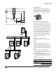
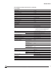
I
t
Long-time Pickup
Instantaneous Pickup
Short-time Pickup
Ground-fault
Pickup
Ground-fault
Delay
Long-time Delay
Short-time Pickup
06313020