
Technical data

11/98
©1995 Square D—All Rights Reserved
10
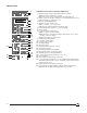
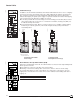
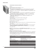
STR 58U Control Unit for Universal Application
1. Mechanical pop-out type fault indicator and reset button:
n Indicates that a fault trip has occurred
n Prevents closure of the circuit breaker after fault until reset
2. Switch selector for the type of fault to be remotely indicated and reset
flat push button (see option FV, p. 15)
3. Ammeter (LCD digital display)
4. Ammeter selector used to read:
n Phase currents (1, 2, 3, N, ground)
n Or the phase with the highest load current (max.)
5. Load indication (bar graph in % of current setting)
6. Sensor rating
7. Local and remote pre-trip alarm:
n LED on at 90% of current setting
n LED flashing on overload (according to time current curves: 105%
to 120% of current setting)
n Remote indication by static contact
8. Rating plug (on STR 58UP)
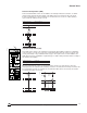
9. Long-time current setting
10. Long-time delay setting
11. Short-time pickup
12. Short-time delay
13. Thermal memory min./max. selector
14. Instantaneous pickup
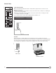
15. Ground-fault (option T or W) pickup
16. Ground-fault (option T or W) time delay
17. Available space for setting identification
18. Load monitoring (option R) pickups (see p. 16)
19. Test receptacle
20. Fault indicator saving battery (option PIL)
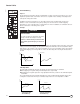
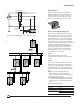
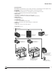
21. Local (option F) fault indicators consist of built-in light emitting diodes
which differentiate the three causes of tripping: overload, short circuit
and ground fault, if any
22. Fault indicator reset or battery test button
23. Fault indicator reactivating button (with PIL option, fault-indicator
lights (21) will only light up when this button is pushed in)
06313019
1
2
3
5
6
7
8
9
10
11
12
13
14
15
16
17
18
19
20
push to reset
I+T
L+I
I
L+T
L
off
T
L+I+T
I
I1 I2 I3
90%
50%
20%
STR 58 U
Ir tr
90
105
τ
tr
%Ir
.88
.9
.92
.95
.98
1
.8
.85
xIo
60
120
240
480
15
30
at 1.5Ir
Im tm
3
45
6
8
101.5
2
xIr
.3
.4 .3
.1
.1
.2
on I
2
t off
.2
0
Ir fault
tr
Im fault
tm
I
fault
Ih
th
t
i
test
+ –
– +
T
R
F
test
Ih
1200A Max
th
400
500 600
800
1000
1200
250
320
A
.3
.4 .4
.2
.1
.2
on I
2
t off
.3
.1
I
8
12 14
19
22
Max.2
4
xIn
Ic1 Ic2
.86
.9 .93
.95
.98
1.8
.85
xIr
.7
.8
.85
.95
.5
.6
.9
1
xIr
V
Ir :
Im :
th :
min.
norm
overcurrent
ground
reset V
4
21
22
23
Control Units