
Technical data

9
©1995 Square D—All Rights Reserved
11/98
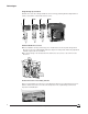
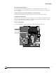
Control Units
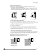
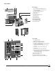
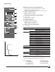
STR 38S Control Unit for Selective Application
1. Mechanical pop-out type fault indicator and reset button:
n Indicates that a fault trip has occurred
n Prevents closure of the circuit breaker after fault until reset
2. Ammeter (LCD digital display)
3. Ammeter selector used to read:
n Phase currents (1, 2, 3, N, ground)
n Or the phase with the highest load current (max.)
4. Load indication (bar graph in % of current setting)
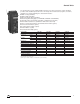
5. Sensor rating
6. Local and remote pre-trip alarm:
n LED on at 90% of current setting
n LED flashing on overload (1)
n Remote indication by static contact
7. Rating plug (on STR 38SP)
8. Long-time current setting
9. Short-time pickup
10. Short-time delay
11. Instantaneous ON/OFF selector
12. Available space for setting identification
13. Ground-fault (option T) pickup
14. Ground-fault (option T) time delay
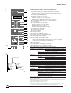
15. Local (option F) fault indicators consisting of built-in light emitting
diodes; fault indicators differentiate the three causes of tripping:
overload, short circuit and ground fault, if any
16. Test receptacle
17. Fault indicator saving battery (option PIL)
18. Fault indicator reset or battery test button
19. Fault indicator reactivating button (option PIL) (2)
06313018
06313017
push to reset
I
I1 I2 I3
90%
50%
20%
STR 38 S
Ir
90
105
%Ir
.88
.9
.92
.95
.98
1
.8
.85
xIo
Im tm
3
45
6
8
101.5
2
xIr
.3
.4 .3
.1
.1
.2
on I
2
t off
.2
0
Ir fault
tr
Im fault
tm
I
fault
Ih
th
t
i
test
+ –
– +
T
F
test
Ih th
400
500 600
800
1000
1200
250
320
A
.3
.4 .4
.2
.1
.2
on I
2
t off
.3
.1
I
offmax.
xIn
Ir :
Im :
th :
1
2
4
5
6
7
8
9
10
12
11
13
14
15
16
17
19
overcurrent
ground
3
18
I
t
Ground-fault
Pickup
Ground-fault
Delay
Long-time Setting
Short-time
Pickup
Short-time Delay
Instantaneous
Overcurrent Protection—RMS sensing
Long-time Current Setting STR 38SP: 0.8 to 1 x Rating Plug (Pickup at 1.1 x Setting)
STR 38S: 0.4 to 1 x Current Sensor (Pickup at 1.1 x Setting)
Delay Fixed: 7.5 sec. at 6 x Current Setting
Thermal Memory as Standard
Rating Plug 4 to 6 Rating Plugs Available Per Sensor Rating: See STR 28D Control Unit, p. 8
Short-time Pickup 1.5 to 10 x Current Setting
Delay Bands 0–0.1–0.2–0.3–0.4 with I
2
t OFF
0.1–0.2–0.3 with I
2
t ON
Instantaneous Pickup High-set Fixed Type (3)—Defeatable on N1 and H1 Types
Ground-fault Protection (Option T or W) (4)
Pickup 0.1 x Current Sensor to 1200 A (5)
Delay Band 0.1–0.2–0.3–0.4 with I
2
t Ramp ON/OFF Switch
Fault Indicators (Option F)
Not Discriminated Local Mechanical Pop-out Type Indicator and LED Pre-trip Alarm
Remote Overcurrent Trip and Pre-trip Alarm Switches (see pp. 14–15)
Discriminated Local With Option F (see p. 14)
Built-in Ammeter (Option I)
Values Display Phase 1, 2, 3, Max., Neutral and Ground Current
Accuracy ±1.5% (6)
Bar Graph Indication Phases 1, 2, 3—10% steps
Control Power Not Required (7)
(1)According to time current curves: 105% to 120% of current setting.
(2)With PIL option, fault indicator lights (15) will light up only when this button is pushed in.
(3)See values on pp. 38–40.
(4)Residual scheme (T). The maximum ground-fault pickup meets 1999 National Electrical Code paragraph
230-95 (a) (not exceeding 1200 A). Source Ground Return scheme (W) on request.
(5)0.1 minimum pickup requires 24 Vdc external power.
(6)Total accuracy including current sensors: ±4.5%.
(7)Control power not required for loads greater than 20% of current sensor. Required for loads less than
20% of current sensor if maximum demand memory requested (see diagram, p. 43).