MASTERPACT® Universal Power Circuit Breaker Class 631 CONTENTS Description Page Introduction ............................................................................................................... 1 Advantages ............................................................................................................... 3 Description ................................................................................................................ 6 Control Units ......................................
Introduction Standard Compliance n UL489: MP08 to MP50 circuit breakers and their accessories are Listed under UL files E63335, E103955 and E113555 n UL1066/ANSI: MC08 to MC50 circuit breakers are UL Listed according to UL1066 (ANSI C37-13) under file E161835 n International Standards: the MASTERPACT® circuit breaker has been designed to meet all the major standards including: IEC 947-2 and related standards such as VDE, BS, EN, etc.
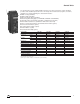
Introduction Ratings Type Ampere Rating (A) MP/MC08 800 Sensor Ratings (A) 250–400–600–800 MP12 1200 800–1200 MP/MC16 1600 1200–1600 MP/MC20 2000 1600–2000 MP25 2500 2000–2500 MP30 3000 2500–3000 MC32 3200 2500–3200 MP/MC40 4000 2500–3000–4000 MP/MC50 5000 4000–5000 MP63 6300 5000–6300 Interrupting Ratings UL489/NEMA AB1 Type Rating (A) 480 Vac 600 Vac Short-time Standard Interrupting Rating MP08 H1 800 65 kA 65 kA 50 kA MP12 H1 1200 65 kA 65 kA 50 kA MP16 H1
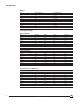
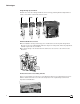
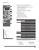
Advantages Drawout Circuit Breaker Design n The drawout assembly mechanism allows the circuit breaker to be racked in four positions (connected, test, disconnected and withdrawn). n The closing and opening push buttons, the racking handle and racking mechanism are accessible 06313005 06313004 06313003 through the front door cutout. Therefore the circuit breaker can be disconnected without opening the door and accessing live parts.
Advantages Single Design up to 6300 A All frame sizes have been designed with the same technology featuring identical depth and door cutouts, and common control units and accessories. 40-50 32 08-30 06313008 63 IG LI L G off LIG I reset V push to reset LG masterpact I O I3 I2 I1 90% push OFF I push ON STR 58 U tr Ir .92 .95 60 .9 .88 Io=3000A %Ir .98 30 .85 1 .8 xIo cat. no. 54775 for masterpact with sensors Im 5 4 3 2 1.5 I Ir fault 6 .3 8 .
Advantages Disconnecting through Door The racking handle and racking mechanism are accessible through the front door cutout. Disconnecting the circuit breaker will therefore be possible without opening the door and giving access to live parts. Isolation Function by Positive Indication of Contact Status The mechanical indicator is truly representative of the status of all three main contacts.
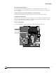
Description 2 Description 3 06313012 1 4 5 13 12 6 11 1. Arc chamber and terminal covers 2. Accessories and control unit front connecting block 3. Position carriage switches 4. Opening coils 5. Arc chute 6. Spring charging motor 7. Front cover 8. Control unit 9. Racking crank 10. Pull-out handgrip 11. Retractable rails 12. Handling handgrip 13. Safety shutters 10 9 8 11 7 Front View 1. 2. 3. 4.
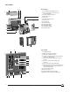
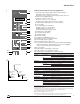
Control Units 06313014 The circuit breaker can be equipped with a microprocessor-based, electronic control unit which provides all the traditional protection of the universal power circuit breaker (long-time, short-time, instantaneous and ground-fault) plus other built-in functions: n RMS sensing (standard) n Alarm switch (standard) n Overcurrent trip switch (standard) n Interchangeable rating plugs (on STR28DP, STR38SP and STR58UP) n Thermal memory and I2t ramp (standard on STR 38-58 control unit) n Defea
06313015 Control Units STR 28D Control Unit for General Application 1 push to reset 1. Mechanical pop-out type fault indicator and reset button: n Indicates that a fault trip has occurred n Prevents closing of the circuit breaker after fault until reset 2. Ammeter (LCD digital display) 3. Ammeter selector used to read: n Phase currents (1, 2, 3, N) n Or the phase with the highest load current (max.) 4. Load indication (bar graph in % of current setting) 5. Sensor rating 6. Rating plug (on STR 28DP) 7.
Control Units 06313017 STR 38S Control Unit for Selective Application 1 push to reset 2 I1 I2 3 4 I I3 90% STR 38 S 5 50% 6 7 8 9 20% Ir 90 .9 .92 .95 .88 %Ir .98 .85 105 1 .8 xIo Im 4 tm .4 5 3 6 .3 2 1.5 8 10 xIr t .3 10 .2 .2 .1 .1 0 on I2t off 11 12 13 I Ir : Ir fault Im : max. tr off xIn th : Ih Ih 500 fault Im fault tm th 600 800 400 320 I 250 A th .3 .4 T .4 14 .3 1000 .2 .2 .1 .
06313019 Control Units V push to reset reset V I+T L+I L off L+I+T I 1 2 T L+T 3 I1 I2 4 I I3 5 90% STR 58 U 6 7 8 9 10 11 50% 20% Ir 90 tr .88 120 .92 .95 60 .85 .9 .98 30 240 %Ir 105 1 .8 Im norm min. τ tr tm .4 5 3 6 .3 2 1.5 8 Ir : 12 .2 .1 .1 0 on I2t off 10 12 .3 .2 xIr I t 4 480 15 at 1.5Ir xIo 13 14 15 14 8 19 Ir fault Im : 4 22 Max.
06313020 Control Units t Overcurrent Protection—RMS Sensing Long-time Current Setting STR 58UP: 0.8 to 1 x Rating Plug (Pickup at 1.1 x Setting) STR 58: 0.4 to 1 x Current Sensor (Pickup at 1.1 x Setting) Delay Bands Long-time Pickup 0.94–1.88–3.75–7.50–15–30s at 6 x Current Setting Thermal Memory as Standard with Min./Max.
06313182 Control Units Thermal Memory push to reset Purpose The thermal memory function allows an optimization of cables or bus bar protection in case of low amplitude repetitive faults. Such faults can be due to repetitive motor startings, fluctuating load or subsequent closing after a fault.
06313021 Control Units Neutral Sensor Main Circuit Breaker T1 T2 S1 S2 06313023 Ground-fault protection may be applied on 3Ø4W or 3Ø3W circuits. On 3Ø4W circuits an external neutral sensor must be used. This neutral current sensor must have the same ampere rating as the circuit breaker sensor. Neutral Ground-fault Neutral CTs S1 T1 S2 T2 Zone-selective Interlocking (ZSI) Option Z on the STR58U control unit provides selective interlocking on short time or ground fault.
Fault Indicator (F) push to reset I1 I2 I3 90% STR 58 U 50% 20% Ir tr xIo Im at 1.5Ir tm xIo t I i Ic1 06313025 xIn Ih T th xIn Ic2 24 Vdc 1W 06313027 In addition to the mechanical fault indicator, this indicator differentiates the three causes of tripping: overload, short circuit or ground fault, if any. Three light-emitting diodes indicate separately longtime, short-time/ instantaneous and ground-fault trip. A flat push button allows resetting of the indicator after tripping.
Control Units Overcurrent Trip Switch (SDE) 06313029 Delivered standard with control unit. In addition to the fault trip indicator/reset button, one SPDT switch provides alarm/lockout information. This SPDT switch is operated only when the circuit breaker is tripped by the control unit. When the circuit breaker is reset, the "a" switch (alarm) is open and the "b" switch (lockout) is closed.
06313033 Control Units Load monitoring (R) push to reset Option R provides two independent static contacts which operate when the current exceeds adjustable pickup limits: n When the current exceeds the limit Ic1 (or Ic2), the contact C-R1 (or C-R2) closes following an inverse time characteristic A. n When the current drops below the limit Ic1 (or Ic2), the contact C-R1 (or C-R2) opens with constant time delay (10 seconds) B. These contacts can be used for load shedding, alarms, indications, etc.
Control Units Communication MASTERPACT circuit breakers can be easily connected to a supervising personal computer using the DIGIPACT® system.
Control Units 06313038 SC150 Indication and Control Interface Function The SC150 indication and control interface is used to: n Transmit to the DC150 data concentrator: o Status information (on, off, tripped, tripped due to electrical fault, tripped due to ground fault) for COMPACT CK and MASTERPACT circuit breakers or any other power circuit actuator o The connected or disconnected status of withdrawable COMPACT CK and MASTERPACT circuit breakers o The status of any external contact n Receive commands tr
Control Units SC150 Indication and Control Interface (continued) Technical Data Digital Inputs (24 V, Self-powered by the SC150 Interface) O Auxiliary Switch One Input F Auxiliary Switch One Input SD Auxiliary Switch (Tripping) One Input SDE Auxiliary Switch (Tripping Due to Electrical Fault) One Input CE Auxiliary Switch One Input CD Auxiliary Switch One Input SDV Auxiliary Switch (Tripping Due to Ground Fault) One Input Other Uses One Unassigned Input Electrical Characteristics Voltage (Su
Control Units 06313039 DC150 Data Concentrator Function The DC150 data concentrator is used to: n Centralize all the information supplied by the various communicating devices: o Auxiliary switches and motor operator o SC150 indication and control interface n Make information available to a personal computer or programmable logic controller (PLC) via the MODBUS/JBUS protocol n Log status changes and tripping of the communicating circuit breakers in order to provide the user with a list of time-stamped event
Control Units DC150 Data Concentrator (continued) 1 06313043 2 3 4 6 Description 5 1. 2. 3. 4. MERLIN GERIN Digipact DC150 BBus JBus OK com com error 24V error 7 5. 9600 19200 0 F 1 456 23 F 0 78 9 CD E N°2 AB N°1 CD E 15 78 9 AB 456 23 16 N°1 N°2 8 9 1 14 10 13 12 11 6. 7. 8-9. 10. 11. 12. 13. 14-15. 16.
Control Units Sizing of the DIGIPACT Internal Bus Sizing of the DIGIPACT internal bus depends on two factors: n The number of devices on the bus n The length of the bus Number of Devices As on any communications network, the number of devices that may be connected on the DIGIPACT internal bus is limited. The maximum number of devices is calculated in terms of "communication points." Each type of device represents a number of points indicated in the table below.
Accessories Location Disconnected Position Switches Terminal Block Connected Position Switches Overcurrent Trip Switch 06313046 Auxiliary Switches Opening Coil Closing Coil Heavy Usage Auxiliary Switches Ready to Close Switch V I+T L off L+I+T I reset V push to reset L+I T L+T I I3 I2 I1 90% STR 58 U 50% 20% tr Ir .98 30 .85 %Ir .8 105 Im 1 xIo 2 1.5 norm min. τ tr I 8 Im : 4 tr th : Ih th 19 22 2 320 250 i overcurrent + – – + Max. xIn .4 .4 .
Accessories The MASTERPACT circuit breaker is equipped with a true two-step stored energy mechanism which ensures fast opening and closing operations and complete open-close-open sequence without recharging the mechanism. The MASTERPACT circuit breaker has manual actuators that include a charging handle and push-to-open and push-to-close buttons.
06313049 Accessories Closing Coil (XF) 06313050 This device releases the circuit breaker closing mechanism when the spring is charged. The closing coil is rated for continuous duty. The closing release is supplied on request and can be fitted even on a manual operating mechanism. Remote Close A4 XF A1 Anti-pumping Function When the closing coil (XF) is permanently energized, the circuit breaker remains in the open position after it has been opened, either by manual or electrical operation.
Accessories Opening Coils Three types of voltage releases can be used for remote opening of the circuit breakers: n Shunt trip (MX) n Instantaneous undervoltage trip device (MN) n Time-delayed undervoltage trip device (MNR) Possible Combinations 06313049 Each MASTERPACT circuit breaker can be equipped with: n One shunt trip (MX) + one undervoltage trip device (MN or MNR) n Or two shunt trips (MX) Shunt Trip (MX) This release is rated for continuous duty and operates with control voltages between 85% and
Accessories Time-delayed Undervoltage Trip Device (MNR) (1) To prevent the circuit breaker from tripping in the event of transient voltage drops, this release has a built-in adjustable time delay. If required, this time delay can be overridden by connecting an external switch on an additional circuit (wired by the user). The undervoltage trip device is fieldinstallable.
06313055 Accessories 24 Additional Auxiliary Switches (OFSUP) An external plate holds a set of 24 SPDT switches operated by means of a cable. They are available only for drawout circuit breakers. Standard Auxiliary Switches (O and F) 06313056 2a + 2b switches available as standard: n "a" contacts are open when the circuit breaker is open and closed when the circuit breaker is closed. n "b" switches are closed when the circuit breaker is open and open when the circuit breaker is closed.
Accessories Connected Position Switches (CE) A block of four SPDT switches operate when a drawout circuit breaker is in the connected position. The switch block is field-installable. Disconnected Position Switches (CD) A block of two SPDT switches operate when a drawout circuit breaker is in the disconnected position. The switch block is field-installable. See page 30 for operating diagrams.
Accessories Operating Diagrams Auxiliary Switches 06313061 0 1 2 inch 0 1 2 3 4 5 mm Fully Closed Fully Open Closed Main Contact Position 13/8 in. (35 mm) Between Contacts Open Closed a Heavy Usage (OF) .1 Standard (O) .1 Standard (F) .1 24 Additional (OFSUP) .1 b a b b a .4 3/8 in. (9.5 mm) Between Contacts in Open Position Open Open .2 Closed .4 Closed Open .2 Open Closed .4 Closed Open Open Closed .
Accessories Push Button Locking Device (VBP) This device prevents local manual operation of the circuit breaker by covering the opening and/or closing the push buttons. This locking device can be locked by a padlock or a sealing lead. Open Position Lock (VSKA) 06313063 06313064 A key interlock that locks the circuit breaker in the open position by holding the push button in its depressed position. The key interlock is provided.
Accessories Mechanical Interlocks n Disconnecting When Circuit Breaker Is Closed: During any disconnecting attempt when the circuit breaker is closed, an interlocking device ensures the tripping of the circuit breaker before the actual separation of the main disconnects. The circuit breaker remains, however, operable in the other positions: test, disconnected and withdrawn.
Accessories 06313067 Interlocking Rods and Cables Two or three MASTERPACT circuit breakers can be mechanically interlocked by means of rods or cables. This accessory is mountable on the right side of the circuit breaker. This adaptation can be made on site without modifying the circuit breaker.
Accessories Safety Shutters (VO) Comprising two independent parts, line and load side, the safety shutters automatically block access to the main disconnects when the circuit breaker is in the disconnected, test or fully withdrawn position.
Accessories Interphase Barrier (EIP) Mounted between terminals of the stationary assembly, the interphase barrier prevents arc prolongation to the circuit breaker in the event of a line side fault and isolates the circuit breaker connections in insulated bus bar installations. Transparent Cover (CB) 06313076 06313075 Hinged-mounted and locked with a milled head, this cover is designed to be installed on the door escutcheon.
06313077 Switch Ratings Type Ampere Rating (A) Short-time Rating (RMS Sym. Amperes) 600 Vac Max. Short-circuit Withstand When Protected by a MASTERPACT Circuit Breaker (A) Max. Frame (A) 600 Vac Max.
Trip Curves 9000 8000 7000 6000 5000 5000 4000 4000 3000 3000 Current Setting: STR 28D = 0.4–1 x Sensor Rating STR 28DP = 0.8–1 x Plug Rating 2000 2000 1000 900 800 700 600 1000 900 800 700 600 500 500 400 400 300 300 200 200 100 90 80 70 60 100 90 80 70 60 50 50 40 40 30 30 20 20 10 9 8 7 6 10 9 8 7 6 5 5 4 4 3 3 2 2 Instantaneous Pickup I = 1.5–10 x Ir 1 .9 .8 .7 .6 1 .9 .8 .7 .6 .5 .5 .4 .4 .3 .3 .2 .2 .1 .09 .08 .07 .06 .1 .09 .08 .07 .06 .05 .05 .
Trip Curves .5 .6 .7 .8 .9 1 1.2 1.5 2 3 4 5 6 7 8 9 10 20 30 40 50 60 2 3 4 5 6 7 8 9 10 20 30 40 50 60 70 80 90 100 10000 9000 8000 7000 6000 70 80 90 100 06313079 Overcurrent Protection STR 38S Control Unit 9000 8000 7000 6000 5000 5000 4000 4000 3000 3000 Current Setting: STR 38S = 0.4–1 x Sensor Rating STR 38SP = 0.
Trip Curves 2 3 4 5 6 7 8 9 10 20 30 40 50 60 2 3 4 5 6 7 8 9 10 20 30 40 50 60 9000 8000 7000 6000 9000 8000 7000 6000 5000 5000 4000 4000 3000 3000 Current Setting: STR 58U = 0.4–1 x Sensor Rating STR 58UP = 0.8–1 x Plug Rating 2000 1000 900 800 700 600 1000 900 800 700 600 500 500 400 400 300 300 200 200 100 90 80 70 60 100 90 80 70 60 50 50 40 40 30 30 20 20 10 9 8 7 6 10 9 8 7 6 5 5 Short-time Pickup Im = 1.
Trip Curves 3 4 5 6 7 8 9 10 20 30 40 50 60 600 700 800 900 1000 2 1000 900 800 700 600 Ground-fault Pickup Ih = 0.1 x In 1200 A Max. 500 400 500 400 300 300 200 200 100 90 80 70 60 100 90 80 70 60 50 50 40 40 30 30 20 20 10 9 8 7 6 10 9 8 7 6 5 5 4 4 3 3 I 2t ON 2 Time in Seconds .5 .6 .7 .8 .9 1 1.2 1.5 500 .4 400 .3 300 .2 200 .1 .12 .15 70 80 90 100 1000 900 800 700 600 .05 .06 .07 .08 .
Trip Curves 10000 9000 8000 7000 6000 2 3 4 5 6 7 8 9 10 20 30 40 50 60 10000 9000 8000 7000 6000 5000 5000 4000 4000 3000 3000 Current Setting Ir = 0.8–1 x Plug Rating 2000 2000 1000 900 800 700 600 Ic1 = 0.8 1 x Ir 1000 900 800 700 600 500 Ic2 = 0.5 1 x Ir 500 400 400 300 300 200 200 100 90 80 70 60 100 90 80 70 60 tr1 = tr / 2 50 50 40 40 30 30 tr2 = tr / 4 5 4 4 3 3 2 2 1 .9 .8 .7 .6 1 .9 .8 .7 .6 .5 .5 .4 .4 .3 .3 .2 .2 .1 .09 .08 .07 .06 .1 .
Wiring Diagrams 06313083 Diagram No.
Wiring Diagrams 06313084 Diagram No.
Wiring Diagrams SC150 Indication and Control Interface Motor Operator Power Supply 06313085 To Power Supply "L" 400 630 C1 NO NC ON C2 reset Control Outputs C3 CD CE SDV SD Inputs PT100 Temperature Probe External Contact 24-250V CC 100-440V CA 2 DIGIPACT Internal Bus COM + – NC 0 24V e+ e– T+ T– SC150 Indication and Control Interface Inputs C4 ON IN OFFSDE L To "IN" SC150 Input Terminals 1 4 To "C4" SC150 Input Terminals N To SC150 Terminals "T+" and "T–" To "C3" on SC150 Input Terminals T
Wiring Diagrams DC150 Data Concentrator 06313086 DC150 9600 3456 2 2 1 110–240 Vac 115–125 Vdc A Protection 5 0 78 9A B CD N°2 3456 B 78 9A 0 E N°1 B CD Internal Bus NC Internal Bus – Internal Bus + MODBUS/JBUS Speed 19200 B E 24 V 0V DC150 Address on MODBUS/JBUS Network 6 9 RS485 MODBUS/JBUS C Connectors 06313088 The DC150 concentrator is connected using a SUBD9 male connector with a metal hood (e.g., ITT canon, DE9P K83 + hood or DE115-500-5-RD).
Circuit Breaker Dimensions Door Escutcheon (Drawout Mounting) Drilling of the Door 06313091 06313089 06313090 Door Cutout 6 153 10.63 270 0.75 Basis: 19 MP08 to MP30 2.6 MC08 to MC32 66 1.85 47 1.77 2.17 45 55 12.8 325 2.82 72 MP40 to MP63 MC40/MC50 5.83 0.73 149 19 2.72 69 Mounting Holes 0.19 Dia. ∅5 7.1 180 7.1 180 0.69/ 18 Door Escutcheon (Fixed Mounting) Drilling of the Door 06313094 06313093 06313092 Door Cutout 6 153 10.63 270 2.82 2.82 72 72 2.72 69 1.06 27 Mounting 1.
Circuit Breaker Dimensions External Neutral Sensor 0.7 18 0.7 18 3.15 80 1.75 45 MP25/MP30/MP40, MC32/MC40 06313099 06313098 MP08 to MP20, MC08 to MC20 0.56 Dia. ∅14 0.39/10 MP08 to MP16 MC08 to MC16 1.73 44 0.79/20 MP20/MC20 1.75 45 0.79 20 3.94 100 6.30 160 2.36 60 1.75 45 0.7 18 1.8 46 0.78 20 4.72 120 0.7 18 3.15 80 1.75 45 06313101 06313100 0.7 18 0.56 Dia. ∅14 2.9 74 0.79/20 MP25/MP30/MC32 3.31 84 1.18/30 MP40/MC40 1.75 45 0.79 20 3.94 100 6.30 160 2.36 60 1.75 45 0.
Circuit Breaker Dimensions MP08–MP12–MP16 Fixed Mounting 4.53 115 4.53 3.35 115 85 3.15 0.98 80 0.98 25 25 0.47 Dia. ∅12 06313106 06313105 3-Pole 4.53 115 0.5 Dia. ∅12,7 4.53 115 Note: Suitable for continuous operation at 100% rating in a minimum cubicle space 17.5 in. (440 mm) h. by 21 in. (530 mm) w. by 14.25 in. (360 mm) d. Ventilation is not required. Refer to shop drawing #688 378 for verification. Vertical terminals are optional for MP08–MP12 circuit breakers. 3.35 85 0.
Circuit Breaker Dimensions MP08–MP12–MP16–MC08–MC16 Drawout Mounting 4.53 115 4.53 115 1.87 48 3.15 80 0.98 25 06313114 06313113 3-Pole 4.53 115 0.5 Dia. ∅12,7 4.53 115 Note: Suitable for continuous operation at 100% rating in a minimum cubicle space 17.5 in. (440 mm) h. by 21 in. (530 mm) w. by 14.25 in. (360 mm) d. Ventilation is not required. Refer to shop drawing #688 378 for verification. Vertical terminals are optional for MP08–MP12–MC08 circuit breakers. 1.87 48 0.63 16 0.47 Dia.
Circuit Breaker Dimensions MP20 Fixed Mounting Note: Suitable for continuous operation at 100% rating in a minimum cubicle space 17.5 in. (440 mm) h. by 21 in. (530 mm) w. by 14.25 in. (360 mm) d. Ventilation is not required. Refer to shop drawing #688 379 for verification. 06313121 3-Pole 4.53 115 0.79 20 0.56 Dia. ∅14 4.53 115 3.35 85 Necessary Space for Removing the Arc Chutes 17.24 438 3.15 80 06313123 06313122 14.88 378 Cell (Insulation Not Required) 1.57 40 Min. 4.
Circuit Breaker Dimensions MP20–MC20 Drawout Mounting 06313127 3-Pole 0.56 Dia. ∅14 4.53 115 0.79 20 4.53 115 Note: Suitable for continuous operation at 100% rating in a minimum cubicle space 17.5 in. (440 mm) h. by 21 in. (530 mm) w. by 14.25 in. (360 mm) d. Ventilation is not required. Refer to shop drawing #688 379 for verification. 1.87 48 06313129 Withdrawn Position 9.56 1.77 243 45 Disconnected Position 14.21 361 06313128 Cell (Insulation Not Required) 4.53 115 1.75 45 17.32 440 Min.
Circuit Breaker Dimensions MP25–MP30 Fixed Mounting 06313133 3-Pole 0.56 Dia. ∅14 5.85 149 0.25 6 5.85 149 Note: Suitable for continuous operation at 100% rating in a minimum cubicle space 26 in. (660 mm) h. by 21 in. (530 mm) w. by 14.25 in. (360 mm) d. with a ventilation of 30 sq. in. (200 cm2) at top and bottom. Refer to shop drawing #688 380 for verification. 2.01 51 0.25 6 14.88 378 17.24 438 3.
Circuit Breaker Dimensions MP25–MP30 Drawout Mounting Note: Suitable for continuous operation at 100% rating in a minimum cubicle space 26 in. (660 mm) h. by 21 in. (530 mm) w. by 14.25 in. (360 mm) d. with a ventilation of 30 sq. in. (200 cm2) at top and bottom. Refer to shop drawing #688 380 for verification. 3-Pole 06313139 0.56 Dia. ∅14 5.75 146 0.25 6 0.65 17 5.75 146 0.25 6 Withdrawn Position 06313144 9.56 1.77 243 45 Disconnected Position 14.
Circuit Breaker Dimensions MC32 Drawout Mounting 0.25 0.53 Dia. 6 ∅14 6.10 155 6.10 155 Note: Suitable for continuous operation at 100% rating in a minimum cubicle space 22 in. (560 mm) h. by 25.25 in. (640 mm) w. by 14.25 in. (360 mm) d. with a ventilation of 30 sq. in. (200 cm2) at bottom. Refer to shop drawing #689 074 for verification. 2.55 65 0.25 6 06313147 06313145 3-Pole Withdrawn Position 9.56 1.77 243 45 Disconnected Position 14.21 361 Cell (Insulation Not Required) 06313146 2.
Circuit Breaker Dimensions MP40–MP50 Fixed Mounting MP40 1.14 29 0.56 Dia. ∅14 9.76 248 9.76 248 0.25 0.5 6 13 06313149 06313148 3-Pole 5.59 142 0.25 6,35 1.14 29 1.14 29 9.76 248 0.78 20 9.76 248 5.59 142 1.14 29 06313150 MP50 0.25 6,35 1.14 29 9.76 248 9.76 248 0.5 13 5.59 142 1.14 29 0.25 6,35 Necessary Space for Removing the Arc Chutes 06313152 1.57 40 Min. 06313151 29.88 759 Cell (Insulation Not Required) 32.24 819 1.75 44,5 2.28 58 (4) Mounting Holes 0.44 Dia. / Ø11 0.
Circuit Breaker Dimensions MP40–MP50–MC50–MC50 Drawout Mounting 0.25 6 MP40–MC50 9.94 253 9.94 253 1.26 32 0.56 Dia. ∅14 3.94 100 0.25 6 9.94 253 9.94 253 0.25 6 06313154 06313153 3-Pole 3.94 100 1.26 32 0.25 6 0.56 Dia. ∅14 06313155 MP50–MC50 3.94 100 9.94 253 1.26 32 9.94 253 0.25 6 0.56 Dia. ∅14 0.25 6 Withdrawn Position Disconnected Position 9.56 243 1.77 45 14.21 361 0.56 Dia. ∅14 1.75 45 2.28 58 06313157 06313156 Cell (Insulation Not Required) 19.1 485 Min. 10.24 260 4.
Circuit Breaker Dimensions MP40–MP50 Drawout Mounting 4-Pole (Not UL Listed) MP40 9.94 252,5 0.25 6,35 9.94 252,5 1.26 32 3.94 100 0.25 6,35 06313159 06313158 9.94 252,5 0.56 Dia. Ø14,3 9.94 252,5 0.25 6,35 9.94 252,5 9.94 252,5 3.94 100 0.25 6,35 1.26 32 0.56 Dia. Ø14,3 06313160 MP50 9.94 252,5 0.25 6,35 9.94 252,5 9.94 252,5 1.26 32 3.94 100 0.25 6,35 0.56 Dia. Ø14,3 Withdrawn Position Disconnected Position 1.77 45 14.21 361 06313162 06313161 9.56 243 41.38 1051 0.56 Dia.
Circuit Breaker Dimensions MP63 Drawout Mounting (Not UL Listed) 06313163 3-Pole 0.25 6 13.78 350 13.78 350 Note: Refer to shop drawing #688 382 for verification. 4.62 118 2.00 51 0.25 6 0.56 Dia. ∅14 Withdrawn Position 9.56 1.77 243 45 Disconnected Position 14.21 361 06313164 06313165 Cell (Insulation Not Required) 2.28 58 1.75 45 19.1 485 Min. 10.24 260 (6) Mounting Holes 0.44 Dia./∅11 1.57 40 18.70 475 18.70 475 2.16 55 41.14 1045 4.72 120 3.08 78 3.98 101 4.21 107 6.89 175 3.
Circuit Breaker Dimensions Mechanical Interlocks for Drawout or Fixed Circuit Breakers Connecting Links for Two Stack-mounted Circuit Breakers Fixed Mounting 06313175 06313174 Drawout Mounting 1.96 50 1.57 40 2.03 52 4.9 125 1.17 30 1.96 50 0.19 5 0.54 14 4.9 125 35.29 900 Max. 1.17 30 35.29 900 Max. 35.29 900 Max. 6.86 175 4.11 105 6 153 (*) 6.39 163 2.54 65 6.5 166 1.76 45 Circuit Breaker Basis for Rating: MP40 (3-Pole) to MP63, MC40 (3-Pole) 3.21 82 1.
Circuit Breaker Dimensions Connecting Links for Three Stack-mounted Circuit Breakers Fixed Mounting 06313176 06313177 Drawout Mounting 1.96 50 1.57 40 2.03 52 7.05 180 2.35 60 0.19 5 7.05 180 0.54 14 2.35 60 0.54 14 2.35 60 35.29 900 Max. 35.29 900 Max. 1.96 50 50 1.57 40 2.03 52 7.05 180 2.35 60 0.19 5 7.05 180 35.29 900 Max. 35.29 900 Max. 1.96 50 1.96 50 2.54 65 (*) 1.76 45 6.5 166 6.86 175 4.11 105 35.29 900 Max. 1.
Circuit Breaker Dimensions DC150 Data Concentrator 06313179 4 Ø.20 4 Ø5 BBus JBus OK com com error 24V error CD 0 EF 1 456 23 EF 789 CD N°2 AB N°1 0 5.47 139 4.92 125 AB 456 23 9600 19200 789 N°1 N°2 3.94 100 7.60 193 1 3.94 100 1.97 50 06313180 SC150 Indication and Control Interface 1.97 50 4.13 105 6.50 165 2 Ø.20 2 Ø5 2.80 71 4.92 125 6.
Appendix Routine Maintenance Guidelines DANGER HAZARD OF ELECTRICAL SHOCK, BURN OR EXPLOSION. Turn OFF all power supplying the equipment before installing or removing circuit breaker. Failure to observe these precautions will cause death, personal injury or electrical shock. CAUTION HAZARD OF EQUIPMENT DAMAGE. Since circuit breakers contain factory-sealed and calibrated elements. Do not break seal.
Appendix Insulation Resistance Tests When circuit breakers are subjected to severe operating conditions, an insulation resistance test may be performed as indicated in NEMA standard publication No. AB4-1991. An insulation resistance test is used to determine the quality of the insulation between phases and phase-toground. The resistance test is made at a dc voltage higher than the rated voltage to determine the actual resistance of the insulation. The most common method employs a "megger" type instrument.
Appendix Endurances A–Endurance Without Maintenance MASTERPACT MP or MC Mechanical Electrical 08 12 16 20 25 30 - 32 40 50 63 12,500 10,000 10,000 10,000 10,000 10,000 5,000 5,000 5,000 480 Vac 10,000 10,000 10,000 9,000 8,000 4,000 3,000 3,000 2,000 600 Vac 10,000 10,000 10,000 7,000 6,000 2,600 2,500 2,500 1,500 20,000 15,000 15,000 15,000 10,000 10,000 10,000 B–Endurance With Service Maintenance Electrical (480 Vac) or Mechanical 20,000 20,000 C–Endurance R
Appendix IEC 947-2 Interrupting Ratings In addition to UL 489 and ANSI C37-13, MASTERPACT circuit breakers comply with the IEC 947-2 Standard as per the table below. For further information, contact a sales representative.
Appendix IEC 947-2 Ratings Auxiliary and Position Switches Voltage (V) Auxiliary Switch OF 50/60 Hz DC 110 O OFSUP Overcurrent Trip Switch SDE Ready to Close Switch PF Position Switches CE/CD/CT 15 240 10 10 10 10 10 10 380 10 6 6 5 5 6 480 10 6 6 600 6 3 3 48 5 3 3 6 3 3 3 3 125 3 0.5 0.5 0.3 0.3 0.5 250 3 0.25 0.25 0.15 0.15 0.25 500 0.
Notes 67 11/98 ©1995 Square D—All Rights Reserved
Notes 68 ©1995 Square D—All Rights Reserved 11/98
Notes 69 11/98 ©1995 Square D—All Rights Reserved
Notes 70 ©1995 Square D—All Rights Reserved 11/98
Notes 71 11/98 ©1995 Square D—All Rights Reserved
Notes 72 ©1995 Square D—All Rights Reserved 11/98
Square D Company PO Box 3069, 3700 Sixth St SW Cedar Rapids, IA 52406-3069 USA Field Services: 1-800-634-2003 www.squared.com are registered trademarks of Square D Company. POWERLOGIC, Square D and MASTERPACT, COMPACT and MULTI 9 are registered trademarks of Schneider Electric. DIGIPACT is a registered trademark of Merlin Gerin. MODBUS is a registered trademark of Schneider Automation. All other trademarks are the intellectual property of their respective companies.