PROFESSIONAL SERIES Security and Remote Start Installation Guide for models: CA 6150 CA 6550 2009 Audiovox Electronics Corporation. All rights reserved.
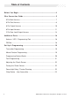
Table of Contents Before You Begin ...................................................................................... 4 Wire Connection Guide ........................................................................... 5 5 Pin Main Harness ................................................................................... 7 6 Pin Start Harness ................................................................................... 8 6 Pin Output Harness .......................................................
Feature Descriptions ............................................................................. 23 Transmitter Button Functions ............................................................. 27 Security Trigger Zones ......................................................................... 28 Remote Start Shutdown Diagnostics ................................................ 28 System Layout .........................................................................................
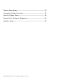
BEFORE YOU BEGIN PROFESSIONAL INSTALLATION STRONGLY RECOMMENDED Installation Precautions: Roll down window to avoid locking keys in vehicle during installation Avoid mounting components or routing wires near hot surfaces Avoid mounting components or routing wires near moving parts Tape or loom wires under hood for protection and appearance Use grommets when routing wires through metal surfaces Use a Digital Multi Meter for testing and verifying circuits.
Pin Main Harness 6 Pin Start Harness 6 Pin Output Harness 2009 Audiovox Electronics Corporation. All rights reserved.
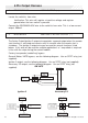
8 Pin Input Harness 3 Pin Lock Output Harness 6 2009 Audiovox Electronics Corporation. All rights reserved.
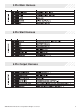
5 Pin Main Harness 1 WHITE/RED PARKING LIGHT INPUT 2 WHITE PARKING LIGHT OUTPUT Locate the parking light output wire at the vehicle’s light switch. Verification: This wire registers positive voltage when the parking lights are turned on. Positive switching Parking Lights: Connect the WHITE/RED wire to a 15 Amp max fused battery source. Connect the WHITE wire to the parking light output wire. Negative switching Parking Lights: Connect the WHITE/RED wire to a good chassis ground.
5 RED BATTERY 12V ( + ) Locate 1 of the vehicle’s constant 12 Volt battery wires at the ignition switch. Verification: This wire will register ( + ) voltage in all positions of the ignition switch. Connect the RED wire to the constant 12 Volt battery wire. NOTE: Remove all fuses until all connections are made. 6 Pin Start Harness 1 PURPLE STARTER OUTPUT ( + ) Locate the vehicle starter wire. Verification: This wire registers voltage only when the key is turned to the START position.
3 RED BATTERY 12V ( + ) Locate 1 of the vehicle’s constant 12 Volt battery wires at the ignition switch. Verification: This wire will register ( + ) voltage in all positions of the ignition switch. Connect the RED wire to the constant 12 Volt battery wire. NOTE: Remove all fuses until all connections are made. 4 PINK IGNITION 1 ( + ) Locate the vehicle’s ignition wire at the ignition switch. Verification: This wire registers voltage when the key is turned to the ON (or RUN) position.
6 Pin Output Harness 1 BROWN/BLACK HORN OUTPUT ( - ) Locate the vehicle’s horn wire. Verification: This wire will register at positive voltage and register ground when the horn switch is pressed. Connect the BROWN/BLACK wire to the vehicle’s horn wire. This is a low current output, 500mA.
3 VIOLET/BLACK AUX 1 This wire provides a ( - ) 500mA output capable of driving relays. For Control of optional accessories (i.e. Power Window/Sunroof, etc.). To activate refer to the transmitter button configuration chart. Please refer to the selectable options for timing. 4 RED/WHITE TRUNK RELEASE OUTPUT ( - ) Locate the vehicle’s trunk release wire at the trunk release switch. Verification: This wire will register either positive voltage or ground when the trunk release is activated.
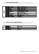
2 GREEN DOOR TRIGGER INPUT ( - ) Locate the vehicle’s dome light or door pin switch wire. Verification: This wire will register ground (NEG) when the door is opened and the interior light is on. This wire will register positive voltage when the door is closed and the interior light is off. Connect the GREEN wire to the vehicle’s negative door input wire(s). NOTE: Certain vehicles may require multiple connections.
6 BLACK/WHITE NEUTRAL SAFETY INPUT ( - ) Locate the vehicle’s neutral safety circuit. Verification: This wire registers ( - ) voltage when the vehicle’s gear selector is in park or neutral. Connect the BLACK/WHITE neutral safety input wire to the neutral safety wire of the vehicle or an optional toggle switch. The remote start feature will not operate unless this input is supplied with a ground source.
3 Pin Lock Output Harness 1 BLUE UNLOCK ( - ) 3 GREEN LOCK ( - ) The door lock / unlock outputs are designed to control several different types of systems which may require additional parts. Please review the wire and location chart to see which type of door lock system is in your vehicle. The most common types are shown in the following diagrams. Negative Switching Locks All Door Lock and Unlock: Locate the lock / unlock wire at the vehicle’s lock / unlock switch.
Positive Switching Locks All Door Lock and Unlock: Locate the lock / unlock wire at the vehicle’s lock / unlock switch. Verification: These wires will register positive voltage when the Lock and Unlock switches are activated. Connect the GREEN and BLUE wires shown in the diagram below.
Negative Multiplexed Locks All Door Lock and Unlock: Locate the lock / unlock wire at the vehicle’s lock / unlock switch. Verification: This wire will show variable ground when the switch is activated. Please consult the wire and location chart for specific resistor values for your vehicle. Connect the GREEN and BLUE or BLUE/GREEN wires shown in the diagram below using (2) SPDT relays (not supplied).
Adding Aftermarket Actuators After installing aftermarket actuators, (not supplied). Connect the GREEN and BLUE wires shown in the diagram below using (2) SPDT relays (not supplied). Fused +12 Volt Battery Source 87 Door Lock Actuator 87a GREEN (-) Lock Output 85 86 30 Chassis Ground M Fused +12 Volt Battery Source 87 87a BLUE (-) Unlock Output 85 86 30 Chassis Ground 2009 Audiovox Electronics Corporation. All rights reserved.
Additional Ports Antenna / LED / Programming Port Mount the supplied antenna/receiver to a clear spot on the vehicle's windshield that will not block the driver's vision. A good location is usually high on the windshield near the rear view mirror. Be careful not to mount the antenna/receiver on any metallic window film, as this will effect system range. Route the antenna/ receiver cable to the control module and plug into the antenna port.
Set Up & Programming Transmitter Programming - Feature Bank 1 1. Turn the ignition ON. 2. Press and hold the valet/override button. 3. Within 10 seconds the system will chirp (3) three times. 4. Press 1 button of each transmitter you wish to program. 5. The system will respond with 1 chirp for each accepted transmitter. 6. Pressing the override button at anytime during programming will advance to the next bank. NOTE: The system will exit transmitter programming after 15 seconds of inactivity.
Defaulting All Features: Pressing the button anytime while in any of the feature banks will default all features and return you to feature bank 2 - 4 chirps. NOTE: The system will remain in feature programming mode as long as the ignition is on, there is no time limit. To exit programming turn the IGNITION OFF. Feature Bank 1 - 3 Chirps Transmitter Programming Refer to transmitter programming. 20 2009 Audiovox Electronics Corporation. All rights reserved.
Tach Programming The unit will not operate unless tach is programmed or tachless option is turned ON. If an attempt is made to start the vehicle via the remote start without first programming tach, the unit will flash the parking lights 7 times indicating tach has not been learned and stored. If the tach rate is not properly programmed to the specific vehicle, the unit may not realize that the vehicle is running in certain instances and reengage the starter motor.
NOTE: If the unit fails to learn tach rate due to an improper tach connection or a poor tach source, the parking lights will not flash. To correct this situation, locate and connect the PURPLE/WHITE wire to the proper tach signal, and then repeat the tach learn routine. Adjusting the Shock Sensor 1. Increase sensitivity by turning the adjustment dial clockwise. 2. Decrease sensitivity by turning the adjustment dial counter clockwise.
Feature Descriptions Feature Bank 2 - Security 1 - Silent Choice: Controls the normal arm/disarm chirps of the security system. ON - Silent arming/disarming upon first press of lock/unlock, pressing lock/ unlock a second time will activate the arm/disarm chirps respectively. The system will only sound the arm/disarm chirps upon a second press of the lock/unlock buttons. OFF - normal arm/disarm chirps upon the first press of lock/unlock.
Feature Bank 3 - Output Control 1 - Extended Lock Pulse: Controls the timing of the BLUE and GREEN lock output wires. 1 Second - Single 1 second lock pulse, single 1 second unlock pulse. 3.5 Seconds - Single 3.5 second lock pulse, single 3.5 second unlock pulse. 1 Second Lock, Double Pulse Unlock - Single 1 second lock pulse, double 1 second unlock pulse. 30 Second Lock, Double Pulse Unlock - Single 30 second lock pulse, double 1 second unlock pulse.
6 - AUX 1: Controls the VIOLET/BLACK AUX 1 output activation type and timing. Push and Hold - Output is continuously active until transmitter button is released. Latched - Output stays active until button is pressed again. Latched until IGN ON - Output stays active until the ignition is turned on. Dome Light Output - Output is used for illuminated entry and is not controlled by the AUX 1 function of the transmitter.
5 - Voltage Level: The voltage variance for remote start when set to tachless. (see tach mode) HIGH - The variance in battery voltage from before the remote start is activated to after the engine is running must be greater than 0.5 volts. LOW - The variance in battery voltage from before the remote start is activated to after the engine is running may be less than 0.5 volts. 6 - Crank Time: Preset output times for the PURPLE starter wire.
11 - 2 or 3 Hour Start: When activated, the remote start will activate and run for the programmed time and shut down every 2 or 3 hours. 12 - Turbo Timer: When activated, the vehicle will run for the programmed time. OFF 1 Minute 3 Minutes 5 Minutes Transmitter Button Functions * 2 Way Transmitter - CA 6550 Only 2009 Audiovox Electronics Corporation. All rights reserved.
Security Trigger Zones If the security system has been triggered the LED will flash one of the patterns below indicating the zone. LED FLASHES TRIGGER ZONE 2 Flashes Hood / Trunk Input 3 Flashes Door Input 4 Flashes Shock Sensor 5 Flashes Ignition Input Remote Start Shutdown Diagnostics If the remote start shuts down or fails to start, the parking lights will flash one of the patterns below indicating the shutdown input.
CA 6150 / CA 6550 2009 Audiovox Electronics Corporation. All rights reserved.
Audiovox Electronics Corporation. Customer Service 1-800-421-3209 WWW.CODE-ALARM.COM FCC COMPLIANCE This device complies with Part 15 of the FCC rules and with RSS-210 of Industry Canada. Operation is subject to the following two conditions: 1. This device may not cause harmful interference, and 2. This device must accept any interference received, including any interference that may cause undesired operation.